

Intraocular thin lens for anterior chamber installation
a thin lens and anterior chamber technology, applied in the field of intraocular lens, can solve the problems of reducing the overall dimension of the iol, ophthalmic surgeons into tolerable compromises, and the lenticular elements, whatever their size, are still subject to various spherical and thickness aberrations which are not easily corrected, so as to reduce the risk of closure, prevent any pressure on the iris, and eliminate the risk of cataract or iris pigment dispersion
Inactive Publication Date: 2009-07-16
NORDAN LEE T +1
View PDF19 Cites 9 Cited by
- Summary
- Abstract
- Description
- Claims
- Application Information
AI Technical Summary
Benefits of technology
This patent describes an innovative intraocular lens (IOL) designed for use during surgery. It has several technical benefits compared to previous devices: it is easy to install, reduces complications like glare and poor night vision, and does not require significant modification after placement. The lens consists of a thin layer made of flexible material that passes through a small opening in the cornea without applying much pressure on the surrounding tissues. It also includes a unique structure called a diffractive phase Fresnel-type lens that helps improve image quality. Additionally, the lens can have various levels of power to address common refractive errors. Overall, this new technology provides better outcomes and minimizes risk associated with ophthalmic procedures.
Problems solved by technology
The technical problem addressed in this patent text relates to developing an intraocular lens (IOL) that can be implanted without requiring a complex multi-piece design or minimizing its effectiveness due to limitations on its size. Current conventional IOLs require precise fitting based on the size of the patient's eye, leading to potential visual difficulties if there is no close fit. Additionally, current IOL designs often result in unwanted astigmatism and other distortions that cannot be corrected during production.
Method used
View moreImage
Smart ImageViewing Examples

Examples
example
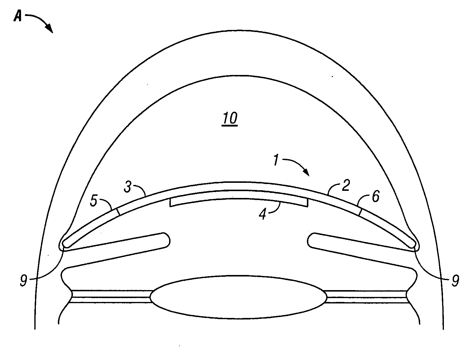
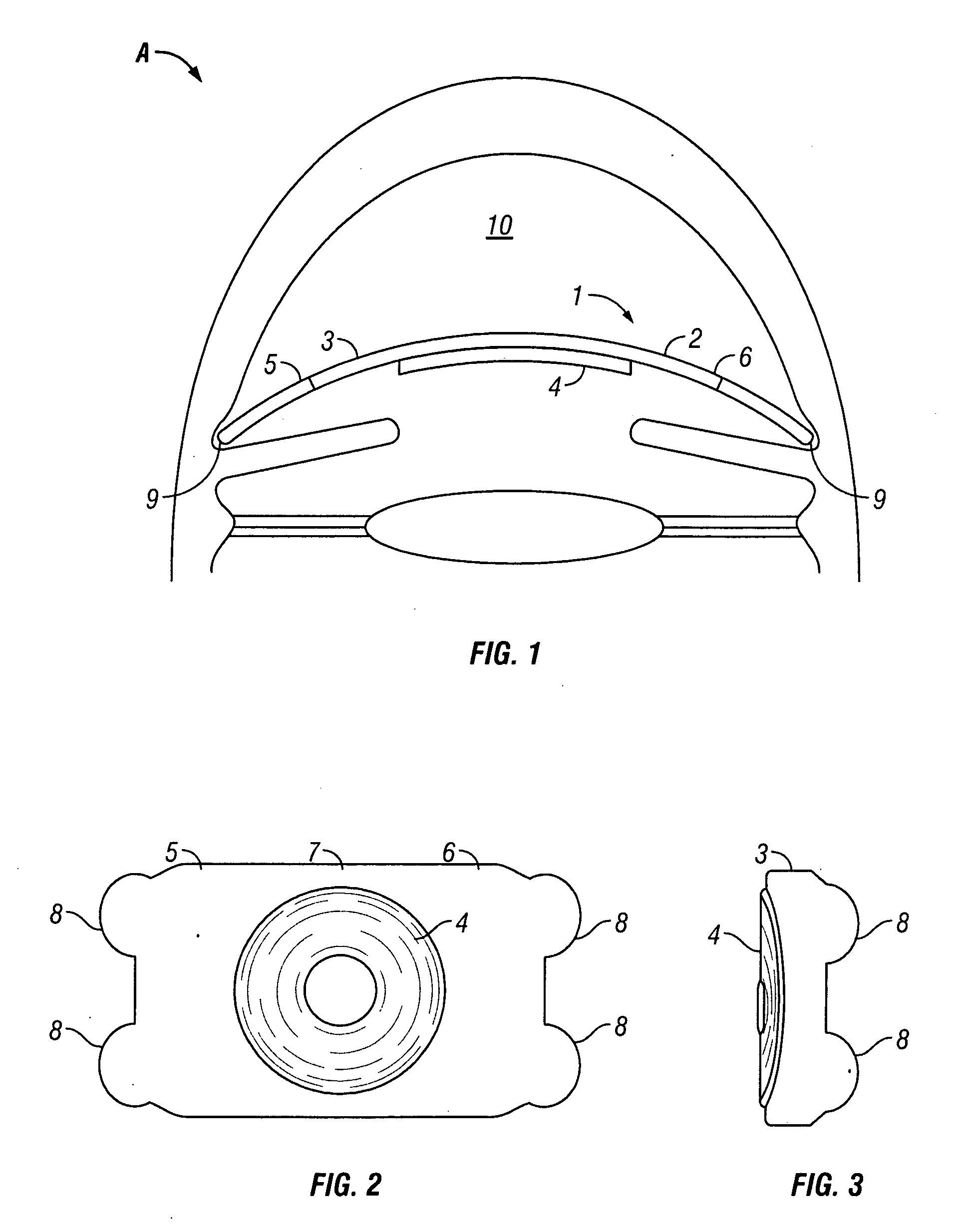
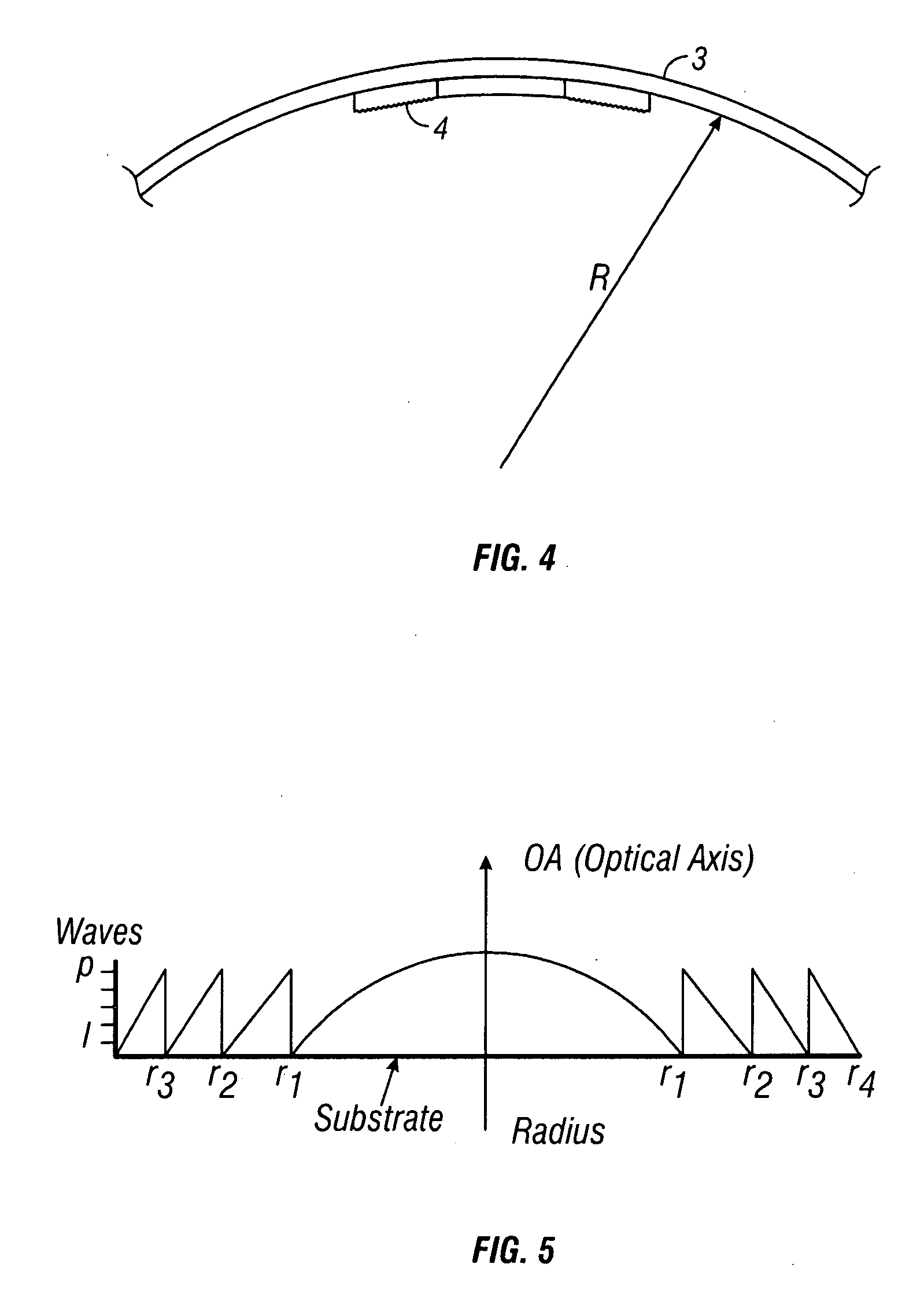
[0024]A thin, foldable, MOD diffractive, polychromatic, intra-ocular implant according to the invention with the following parameters exhibits the following characteristics:[0025]Material: NuSil-MED-6820[0026]Thickness: optic layer 45 microns[0027]Thickness of Substitute: 300 microns[0028]Diameter of corrective portion: 0.65 centimeter[0029]Power: −6 diopters[0030]Number of concentric zones: 50
[0031]Radial location and width of each zone:
Login to View More PUM
 Abstract
A thin foldable intraocular implant specifically configured for installation into the anterior chamber of a phakic or pseudophakic eye has broad positioning flaps that do not apply any substantial pressure against the wall of the eye. It can be rolled for insertion through a corneal incision as small as 2.75 millimeters. The implant is constituted by a two-layered resiliently flexible membrane having a corrective layer of about 50 to 130 microns and an overall thickness of about 150 to 530 microns, that vaults the iris without contacting it. The optic is constituted by a multi-order diffractive (MOD) structure, and is made of silicone, PMMA, hydrogel or hydrophobic acrylate.
Description
Login to View More Claims
Login to View More Application Information
Patent Timeline
 OwnerNORDAN LEE T