
Open state maintainable valve device for an inflatable article

a valve device and inflatable article technology, applied in the direction of functional valve types, valve seats, couplings, etc., can solve the problems of inconvenient the diaphragm is likely to disengage from the retaining flange and close the valve seat, and achieve the effect of facilitating deflation of inflatable articles

Active Publication Date: 2009-07-23
APEX BILLION INTL INV
View PDF9 Cites 2 Cited by
  • Summary
  • Abstract
  • Description
  • Claims
  • Application Information

AI Technical Summary

Benefits of technology

[0006]The object of the present invention is to provide a valve device with a diaphragm that can be kept in a deflected position to maintain the valve device in an open state for facilitating deflation of an inflatable article.

Problems solved by technology

However, with such a valve device, deflation of the inflatable article is inconvenient.
However, only a small portion of the diaphragm in the vicinity of the connecting surrounding portion is retained by the retaining flanges, so that the diaphragm is likely to disengage from the retaining flanges and close the valve seat by a large deflating force during deflation.
Therefore, the user has to depress the diaphragm repeatedly, which is very inconvenient.

Method used


Image

  • Open state maintainable valve device for an inflatable article
  • Open state maintainable valve device for an inflatable article
  • Open state maintainable valve device for an inflatable article

Examples


Embodiment Construction

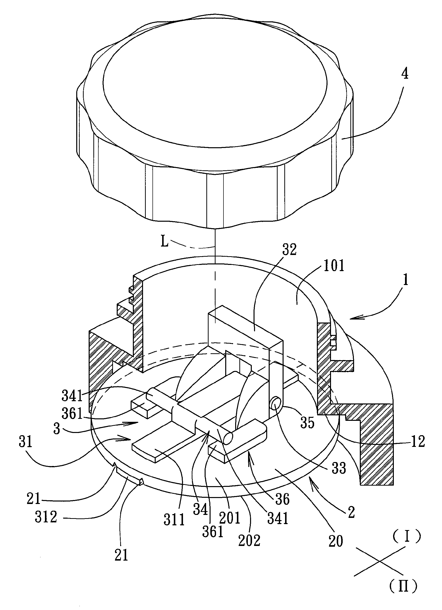
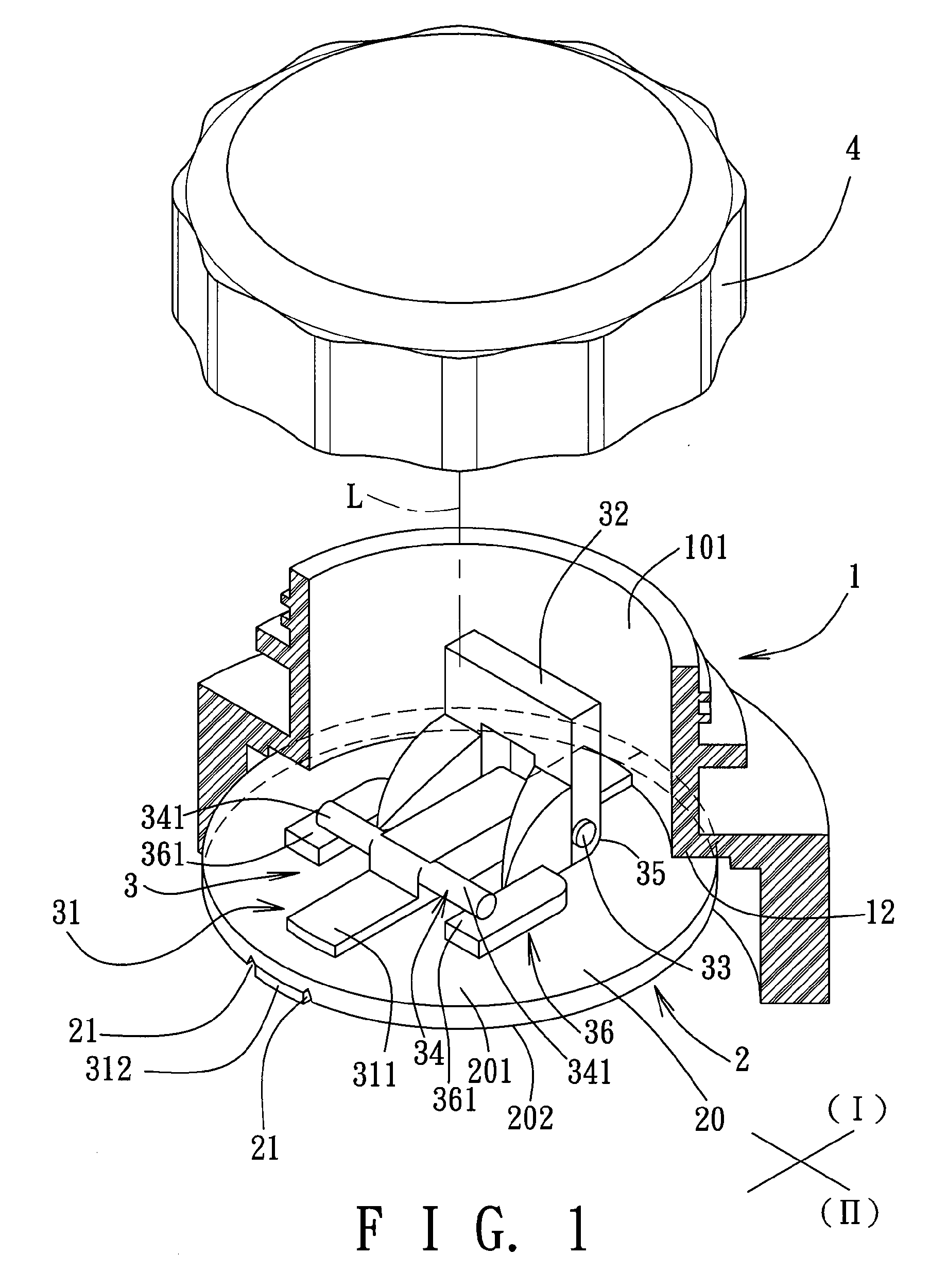
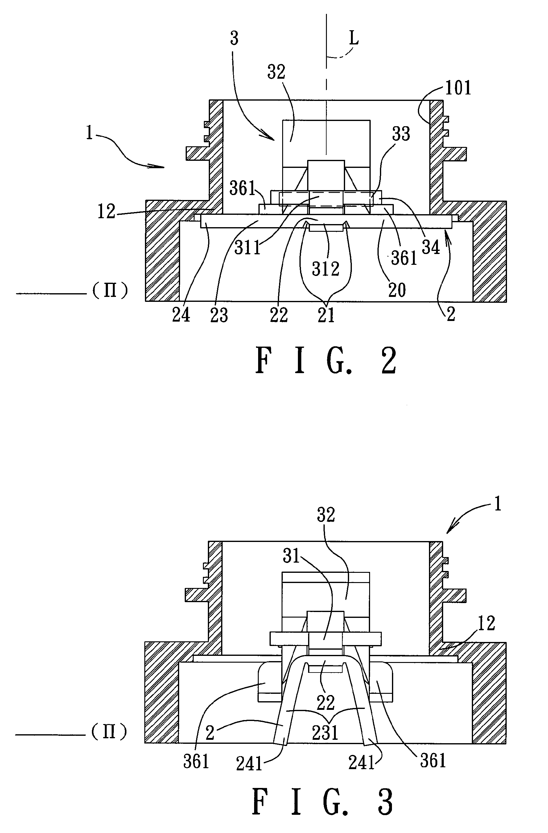
[0014]Referring to FIGS. 1 to 3, the preferred embodiment of a valve device according to the present invention is shown to comprise a tubular member 1, a diaphragm 2, a positioning member 3, and a cap member 4.

[0015]The tubular member 1 is adapted to be fitted into an opening of an inflatable article (not shown) to form an inflating port 101 for an inflatable chamber in the inflatable article. The tubular member 1 extends along a longitudinal axis (L) and terminates at a valve seat 12 that is adapted to face towards the inflatable chamber. As shown in FIG. 4, the valve seat 12 has two abutment areas 121 spaced apart from each other in a first transverse direction (I) transverse to the longitudinal axis (L).

[0016]The diaphragm 2 is made from a flexible material, such as rubber, and has a major wall 20 which has outer and inner major surfaces 201,202 opposite to each other along the longitudinal axis (L) such that the inner major surface 202 confronts the inflatable chamber. The major...


PUM


Abstract

A valve device includes a tubular member fitted into an inflatable article, a flexible diaphragm having a peripheral region which engages a valve seat of the tubular member through a mounting support and an intermediate surrounding region which has a portion that can be flexed to deflect a corresponding portion of the peripheral region from the valve seat, and a positioning member which is actuated to be displaced between normally-closed and deflating positions so as to bring an engaging end thereof to be proximate to or distal from the valve seat. In the deflating position, the flexed portion is vested with an increment of biasing force that is counteracted by a resisting force at an actuated end so as to keep the peripheral portion in a deflected position for maintaining the valve device in an open state.

Description

BACKGROUND OF THE INVENTION[0001]1. Field of the Invention[0002]This invention relates to a valve device for an inflatable article, more particularly to a valve device with a diaphragm that can be kept in a deflected position to maintain the valve device in an open state for facilitating deflation of the inflatable article.[0003]2. Description of the Related Art[0004]A conventional inflatable article is generally provided with a check valve device in an inflating port. The check valve device has a flexible diaphragm that permits air to enter the inflatable article during inflation and that closes the inflating port by virtue of the air pressure inside the inflatable article when the inflation stops. However, with such a valve device, deflation of the inflatable article is inconvenient.[0005]There is provided another conventional valve device that includes a flexible diaphragm which has a connecting surrounding portion attached to a valve seat of a tubular member thereof such that th...

Claims


Application Information

Patent Timeline
Patent Type & Authority Applications(United States)
IPC IPC(8): F16K15/20
CPCF16K15/202Y10T137/3631Y10T137/7839Y10T137/3584
Inventor SONG, RONG-JYHYEN, TSUNG-PING
Owner APEX BILLION INTL INV
Learn More