Valve for inflatable devices

a valve and inflatable technology, applied in the direction of valve arrangements, diaphragm valves, check valves, etc., to achieve the effect of convenient cap retention, low profile and convenient retention of inflating aids

Inactive Publication Date: 2016-08-04
SEA TO SUMMIT PTY LTD
View PDF3 Cites 9 Cited by
  • Summary
  • Abstract
  • Description
  • Claims
  • Application Information

AI Technical Summary

Benefits of technology

[0020]The improved valve may include a cap, the cap operable to act as a further seal for the valve. As with the valve seat, the cap may include second ribs provided on an external surface thereof, such that when the cap is inserted into the interior surface of the valve seat, the second ribs create an interference fit between the cap and the valve seat.
[0021]The valve seat and/or cap may have a tab extending therefrom. The purpose of the component from which the tab(s) extends may be identified by way of one or more of the following: colour; labels; visual texture; tactile texture.
[0022]The valve port is preferably connected to the valve seat by first connecting means in a manner that facilitates the valve

Problems solved by technology

The valve seat may have first ribs provided on an external surface thereof, such that when the valve seat is in

Method used


Image

  • Valve for inflatable devices
  • Valve for inflatable devices
  • Valve for inflatable devices

Examples


first embodiment

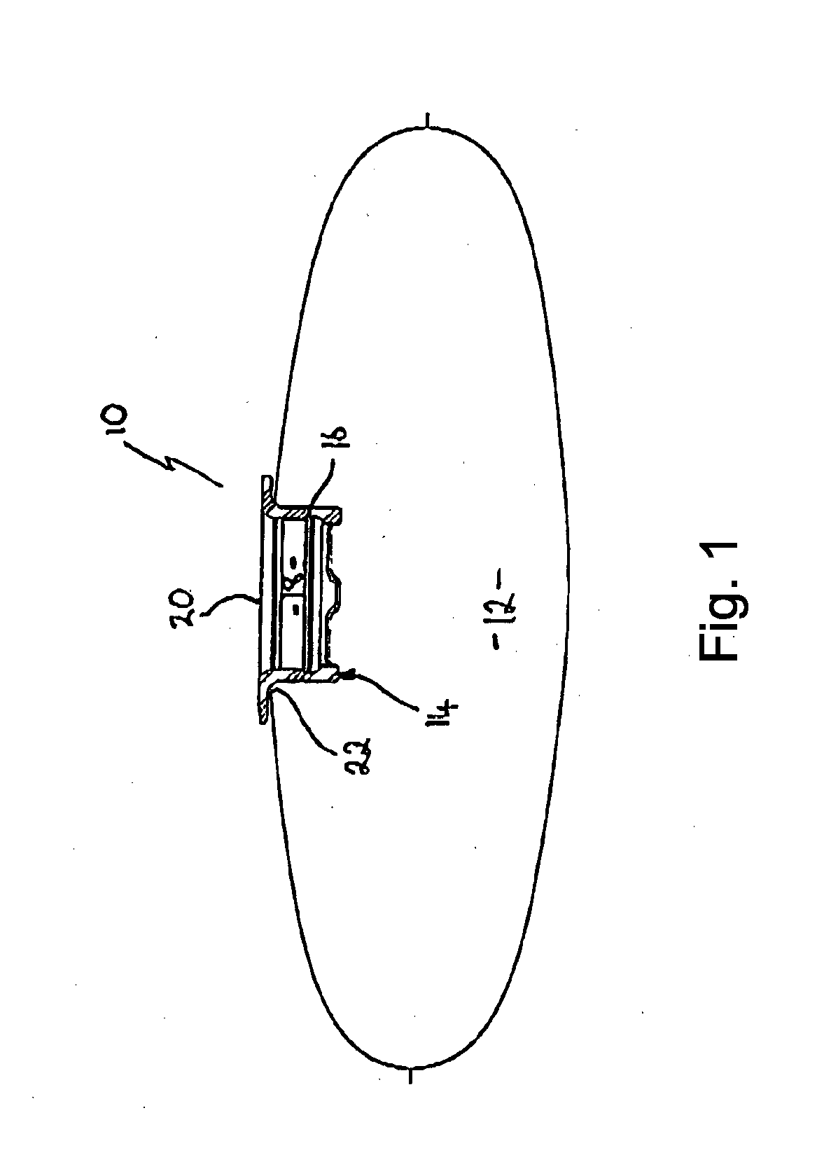
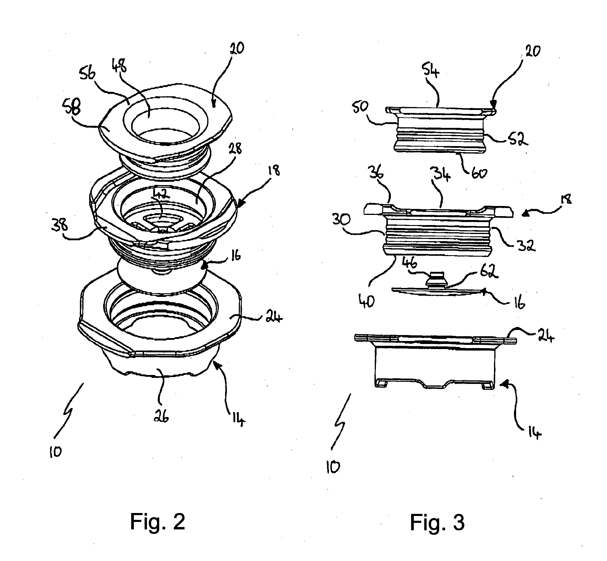
[0037]In accordance with the invention there is an improved valve 10 for inflatable devices 12 comprising:

[0038]a valve port 14;

[0039]a diaphragm 16;

[0040]a valve seat 18; and

[0041]a cap 20.

[0042]The inflatable device 12 has an inflatable compartment. An opening 22 is provided in the inflatable compartment. The opening 22 operates to receive the valve port 14.

[0043]The valve port 14 comprises a flange 24 and a body 26. The body 26 takes the form of a squat hollow cylinder. The flange 24 extends from the circumference of one end of the body 26.

[0044]Following receipt of the valve port 14 within the opening 24 at the time of manufacture, the material from which the inflatable compartment 22 is made is welded to the flange 24. Once welded, the flange 24 operates to conceal and protect the weld.

[0045]The valve seat 18 is cylindrical in shape and has an interior profile 28 and an exterior profile 30. The exterior profile 30 has a plurality of ribs 32 provided thereon. The ribs 32 operate...

second embodiment

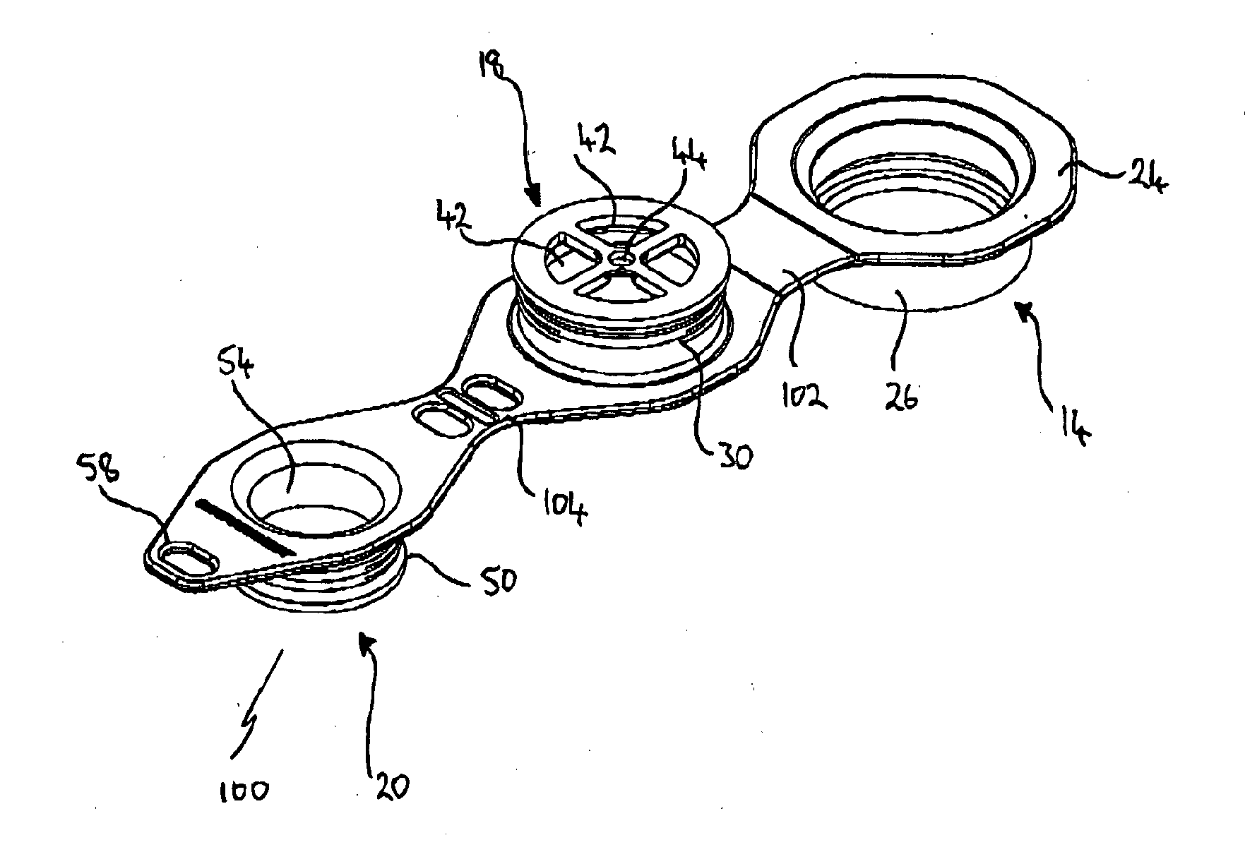
[0063]In accordance with the invention, where like numerals reference like parts, there is an improved valve 100. The improved valve 100 is identical to improved valve 10 save for the following modifications.

[0064]Valve port 14 and valve seat 18 are connected by way of a first flexible connector 102. Flexible connector 102 is connected to side of valve seat 18 opposite first tab 38.

[0065]Valve seat 18 and cap 20 are connected by way of a second flexible connector 104. Flexible connector 104 is connected to the valve seat 18 at a position between the point of connection of the flexible connector 102 and the first tab 38. Flexible connector 104 is connected to the cap 20 at a position opposite second tab 58.

[0066]Manufacture of the improved valve 100 is done on the same principles as described above, but as would be modified by the person skilled in the art to incorporate the flexible connectors 102, 104.

[0067]In use, the improved valve 100 operates substantially as described above. H...


PUM


Abstract

An improved valve for an inflatable device includes a valve port received within an aperture of the inflatable device, a valve seat having fluid apertures provided therein, and a diaphragm connected to the valve seat in a manner that occludes the fluid apertures when fluid is not forced therethrough. The improved valve may, at any time, be manipulated so as to physically remove the valve seat from the valve port to facilitate deflation of the inflatable device and physically insert the valve seat into the valve port to facilitate inflation of the inflatable device.

Description

FIELD OF THE INVENTION[0001]The invention relates to an improved valve for inflatable devices. The invention is particularly suited to use in inflatable devices such as air mattresses and other inflatable outdoor equipment.BACKGROUND TO THE INVENTION[0002]The following discussion of the background to the invention is intended to facilitate an understanding of the present invention. However, it should be appreciated that the discussion is not an acknowledgment or admission that any of the material referred to was published, known or part of the common general knowledge in any jurisdiction as at the priority date of the application.[0003]Inflatable devices take many forms. In some cases, such as where the device is inflatable so as to assist its transport, the use of inflating aids (such as pumps) may be limited if available at all. However, regardless of their use, inflation and deflation of the device is typically through the use of a self-sealing valve.[0004]The typical self-sealin...

Claims


Application Information

Patent Timeline
IPC IPC(8): F16K15/20F16K15/14F16K7/17A47C27/08
CPCF16K7/17F16K15/148A47C27/081F16K15/20F16K15/202F16K15/205
Inventor SANDO, BRENDAN MICHAELSINGH, PARAMJEETTYSON, ROLAND
Owner SEA TO SUMMIT PTY LTD
Why Eureka
Try Eureka