Electroencephalogram interface system and activation apparatus

a technology applied in the field of encoding and encoding electrodes, can solve problems such as the inability to execute a manipulation with both hands

Active Publication Date: 2009-07-23
PANASONIC CORP
View PDF2 Cites 36 Cited by
  • Summary
  • Abstract
  • Description
  • Claims
  • Application Information

AI Technical Summary

Benefits of technology

[0026]In accordance with an electroencephalogram interface system of the present invention, electroencephalograms are observed even while an electroencephalogram interface is not being used, and it is determined whether a steady-state visual evoked potential corresponding to a flicker frequency of a visual stimulation for activation of the electroencephalogram interface (e.g., an icon on a screen or an LED) is appearing on the electroencephalograms or not. If a steady-state visual evoked potential is appearing on the electroencephalograms, the electroencephalogram interface is activated. As a result, at every phase such as activation of the electroencephalogram interface, selection and confirmation of a menu after activation of the electroencephalogram interface, and so on, manipulations via the electroencephalogram interface are possible by utilizing the electroencephalograms of the user. This makes it possible to execute a function based only on electroencephalograms, even in an information device or the like whose screen is occupied at usual times.

Problems solved by technology

However, it has often been impossible to execute a manipulation when both hands are unavailable, due to tasks other than device manipulations, e.g., household chores, rearing of children, and driving an automobile.

Method used


Image

  • Electroencephalogram interface system and activation apparatus
  • Electroencephalogram interface system and activation apparatus
  • Electroencephalogram interface system and activation apparatus

Examples


embodiment 1

[0066]Hereinafter, an electroencephalogram interface system according to the present embodiment will be first described, followed by a description of the construction and operation of an activation apparatus for activating an electroencephalogram interface.

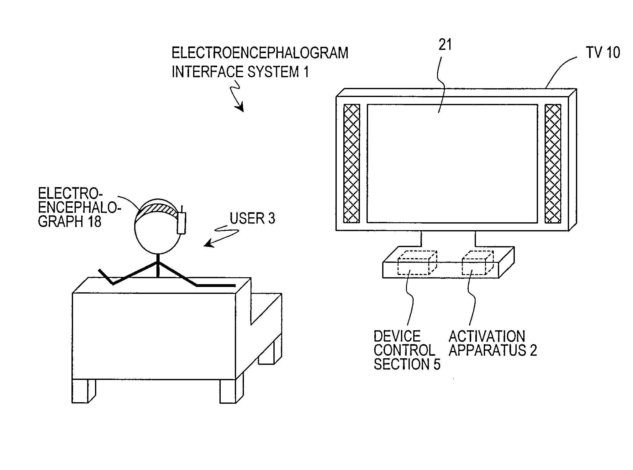
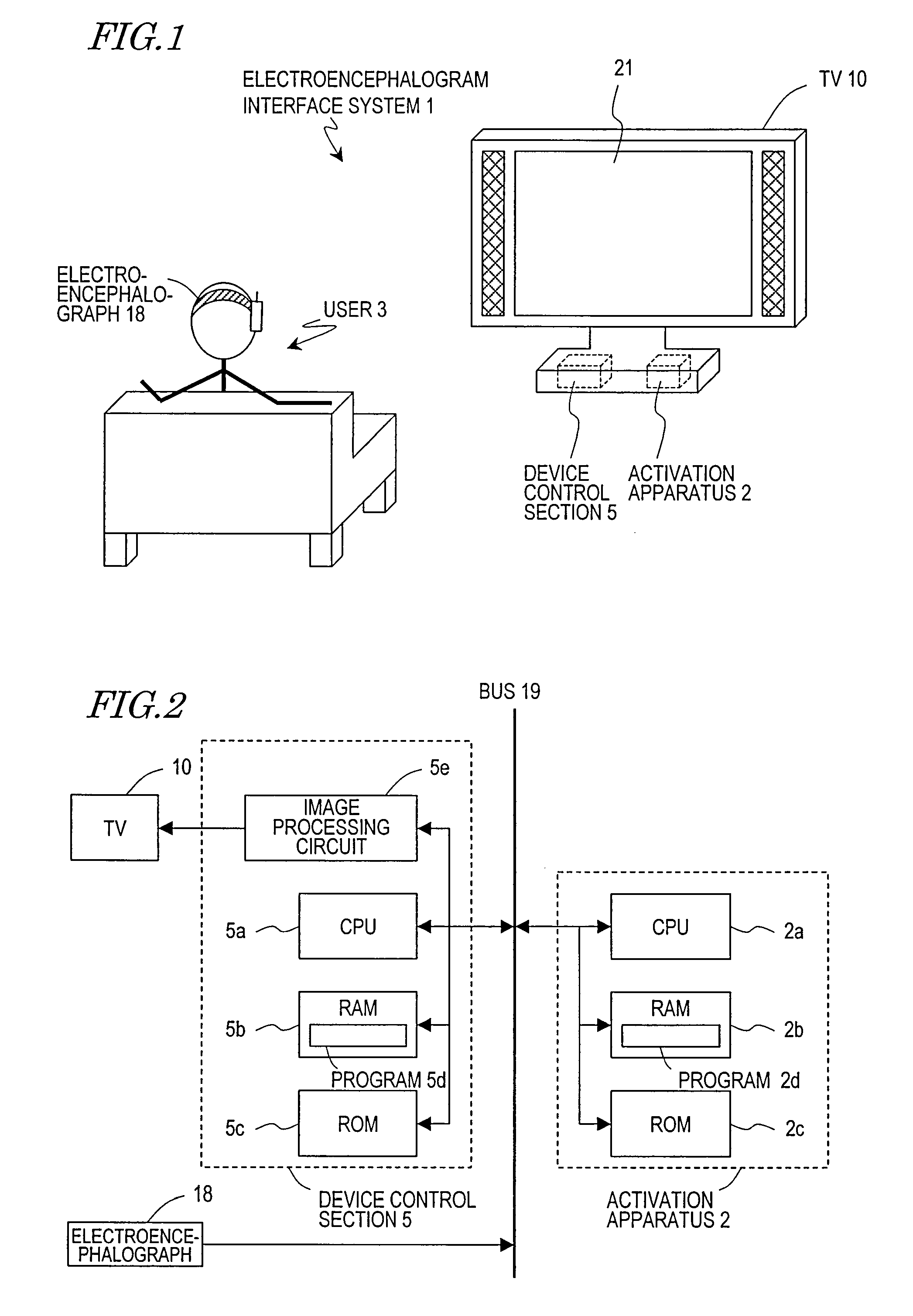
[0067]FIG. 1 shows a construction and an environment of use for the electroencephalogram interface system 1 of the present embodiment. The electroencephalogram interface system 1 is exemplified so as to correspond to the system construction of Embodiment 1 described later.

[0068]The electroencephalogram interface system 1 is used for providing an interface for manipulating a TV 10 by utilizing an electroencephalogram signal from the user 3. An electroencephalogram signal from the user 3 is acquired by an electroencephalograph 18 which is worn on the head of the user 3, and transmitted to a device control section 5 in a wireless or wired manner. The device control section 5 internalized in the TV 10 recognizes an intent of the user ...

embodiment 2

[0120]In Embodiment 1, the flicker frequency of one menu activation icon (or LED) is fixed, and is utilized for the determination as to whether or not to execute an electroencephalogram interface function.

[0121]In the present embodiment and the next embodiment, electroencephalogram interface systems will be described in which the flicker frequency of the menu activation icon is variable, and the flicker frequency is controlled so as to adapt to various situations. Since there is one menu activation icon, there is no need to consider relationships with the flickering of other icons or the like as in Non-Patent Document 2. Moreover, since the icon is allowed to flicker on the TV screen through video signal processing, it is possible, by changing the processing, to change the flicker frequency.

[0122]Note that, in the aforementioned Non-Patent Document 2, a multitude of LEDs having different flicker frequencies are arranged, a frequency which appears in the electroencephalogram signal o...

embodiment 3

[0150]In Embodiment 2, changes in the electroencephalograms are detected by utilizing the fact that changes in a content which is currently presented or a person's state affects the visual evoked potential, and the flicker frequency of a menu activation icon is changed based on the changes in the electroencephalograms.

[0151]In the present embodiment, changes in a content which is currently presented are detected by analyzing the content, and the flicker frequency of a menu activation icon is changed by utilizing this result.

[0152]FIG. 13 shows the functional block construction of the electroencephalogram interface system 11 including the activation apparatus 12 of the present embodiment. In FIG. 13, component elements having the same functions as those of the electroencephalogram interface system 101 in FIG. 10 are denoted by like reference numerals, and the descriptions thereof are omitted.

[0153]In the electroencephalogram interface system 11, an output signal of a content to be pr...


PUM


Abstract

An electroencephalogram interface is activated by utilizing a biological signal, in particular a steady-state visual evoked potential, from a user.
An electroencephalogram interface system (1) includes a biological signal detection section (4) for detecting an electroencephalogram signal from a user (3) and a control section (5) for distinguishing a component of an event-related potential which is contained in the electroencephalogram signal and causing a device to operate based on the distinguished event-related potential. The electroencephalogram interface system (1) further includes an activation apparatus (2) for activating the control section (5) and an output section (6) for presenting a visual stimulation which flickers with a predetermined frequency based on a signal from the activation apparatus (2). The activation apparatus (2) includes: a frequency analysis section (7) for analyzing a frequency component of the electroencephalogram signal detected by the biological signal detection section (4), and detecting an intensity corresponding to the predetermined frequency; and a determination section (8) for comparing the detected intensity of the predetermined frequency and a predetermined threshold, and if the intensity of the predetermined frequency is equal to or greater than a predetermined threshold, determining that the user (3) has been paying attention to the visual stimulation and thus activating the control section (5).

Description

TECHNICAL FIELD[0001]The present invention relates to an electroencephalogram interface system for performing device manipulations by using electroencephalograms. More specifically, it relates to an activation apparatus which is incorporated in an electroencephalogram interface system and activates an electroencephalogram interface by utilizing the electroencephalograms of a user, an activation method, and a computer program which is executed on such an activation apparatus.BACKGROUND ART[0002]To date, various devices have been proposed in our lives. While living among such devices, users enjoy desired information or services by manipulating the devices. Because of an increase in the number of devices themselves, an increase in the information that cannot be obtained without using devices, and so on, the importance of improving the manipulability of such interfaces is increasing year after year. In information devices (television sets, mobile phones, PDAs, etc.), for example, device...

Claims


Application Information

Patent Timeline
Patent Type & Authority Applications(United States)
IPC IPC(8): A61B5/0482A61B5/375G06F3/01H04N5/00H04N5/44
CPCG06F3/015
Inventor MORIKAWA, KOJIADACHI, SHINOBU
Owner PANASONIC CORP
Why Eureka
Try Eureka