Plant grow light with digital timer

a technology of plant grow light and digital timer, which is applied in the direction of fixed installation, lighting and heating apparatus, lighting support devices, etc., can solve the problems of plant stress, increase in heat and light intensity,

Inactive Publication Date: 2009-07-30
GREAT INNOVATIONS
View PDF17 Cites 18 Cited by
  • Summary
  • Abstract
  • Description
  • Claims
  • Application Information

AI Technical Summary

Benefits of technology

[0009]In an example embodiment, the semiconductor device may include at least one memory device that stores at least one program for calculating a clock cycle corresponding t

Problems solved by technology

However, such changes in lamp position may stress a plant due to an increase in heat and light intensity.
Due to variations in the exposur

Method used


Image

  • Plant grow light with digital timer
  • Plant grow light with digital timer
  • Plant grow light with digital timer

Examples


Embodiment Construction

[0019]Referring now to the drawings in which like reference numerals designate like or corresponding parts throughout the several views, there is shown an example embodiment of a plant grow light and digital timer, shown merely for the purpose of illustration. One skilled in the art will readily recognize from the following description, taken in conjunction with the accompanying drawings and claims, that the principles of the present invention may be applicable to other embodiments other than that shown for purposes of illustration in the drawings.

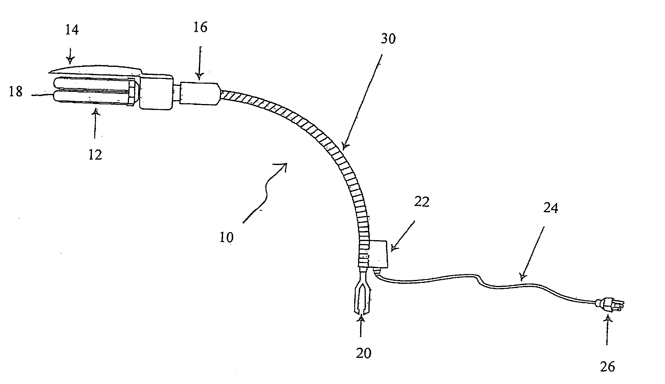
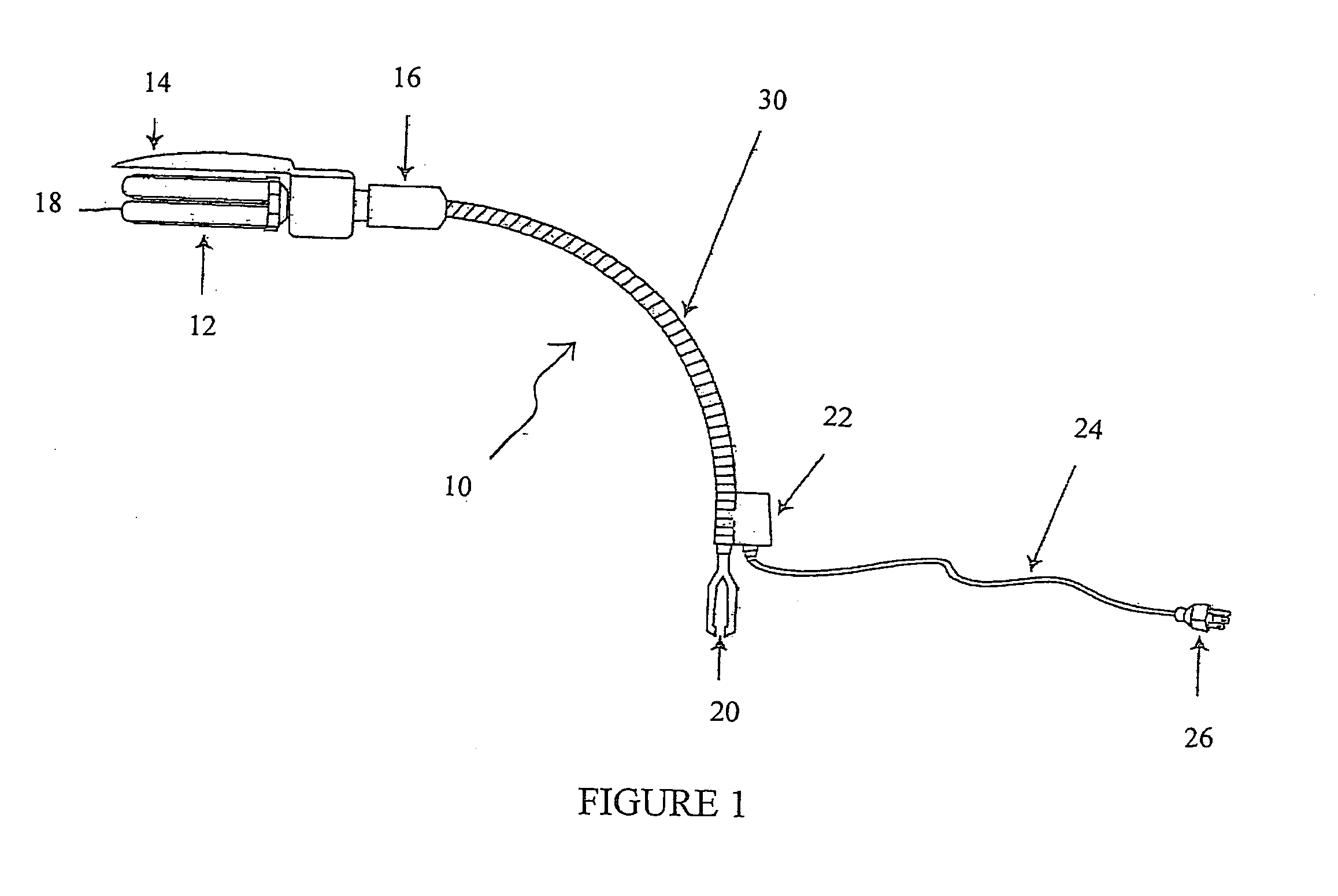
[0020]As shown in FIG. 1 a plant grow light 10 may include a clip 20 to attach the grow light 10 to a plant pot (not shown). A flexible coil 30 may extend from the clip 20 and have a lamp 12 disposed at an end of the flexible coil 30 opposite the clip 20. The lamp 12 is attachable to the flexible coil 30 via a socket 16. The lamp 12 may include one or more bulbs 18 and a light shield 14 disposed over a surface of the bulbs 18. A timer, suc...


PUM


Abstract

A plant grow light attachable to a plant pot that includes a digital timer having a plurality of preset timing positions to cycle the plant grow light on and off according to a desired lighting cycle for a particular plant.

Description

FIELD OF THE INVENTION[0001]The present invention relates to a plant grow light and digital timer. More particularly, the present invention relates to a plant grow light that is attachable to a plant pot and the digital timer to control an amount of exposure to light for a desired plant.BACKGROUND OF THE INVENTION[0002]Indoor gardening often requires artificial lighting to stimulate and maintain proper plant growth. By using the proper lighting conditions plants, flowers, fruits & vegetables may be grown indoors year round. The lighting requirements may be provided for by artificial, rather than natural, light by using a plant grow light. However, lighting requirements may vary greatly depending the age genus and / or species of the plant. For example, some plants do well with up to 12 hours of light a day, while other plants may require up to 16 hours of light per day.[0003]Additionally, depending on the frequency and wattage of a lamp in the plant grow light, the position of the lam...

Claims


Application Information

Patent Timeline
IPC IPC(8): F21V21/14F21S8/00
CPCA01G9/26A01G7/045A01G9/249Y02A40/25Y02P60/14
Inventor MCDONNELL, JOSEPHMCDONNELL, JULIE
Owner GREAT INNOVATIONS
Why Eureka
Try Eureka