High visibility ripper assembly and machine using same

a technology of ripper and assembly, applied in the field of ripper assembly, can solve the problems of difficult design, difficult to achieve, and often compromised visual factor,

Inactive Publication Date: 2009-08-13
CATERPILLAR INC
View PDF22 Cites 11 Cited by
  • Summary
  • Abstract
  • Description
  • Claims
  • Application Information

AI Technical Summary

Benefits of technology

[0006]In another aspect, a machine includes a ripper assembly attached to a back of a track type tractor that includes an operator station. The ripper assembly includes a beam assembly with a central ripper shank and tip flanked by a left linkage and a right linkage. At least one hydraulic actuator is included for moving the beam assembly between raised and dig positions. Each of the left linkage and right linkage include an upper member and a lower member extending between the beam assembly and the track type tractor. An initial penetration view of the central ripper tip is unobstructed by the ripper assembly from the operator station when the beam assembly is between the raised position and the dig position, and the central ripper tip is at a ground penetration level. A production ripping view of a portion of the central ripper shank above the ground penetration level is also unobstructed by the ripp...

Problems solved by technology

This visibility factor is often compromised due to a need to cross brace the ripper assembly linkage to absorb side and twisting loads, especially in the case of multi-shank ri...

Method used


Image

  • High visibility ripper assembly and machine using same
  • High visibility ripper assembly and machine using same
  • High visibility ripper assembly and machine using same

Examples


Embodiment Construction

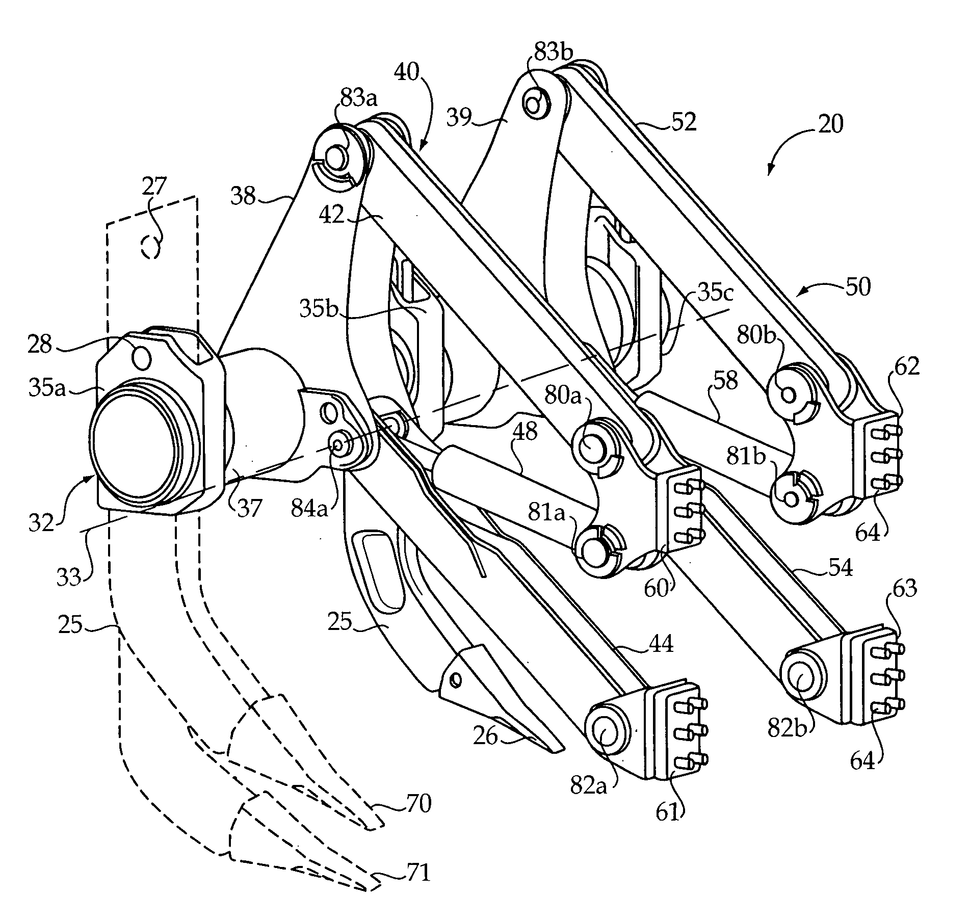
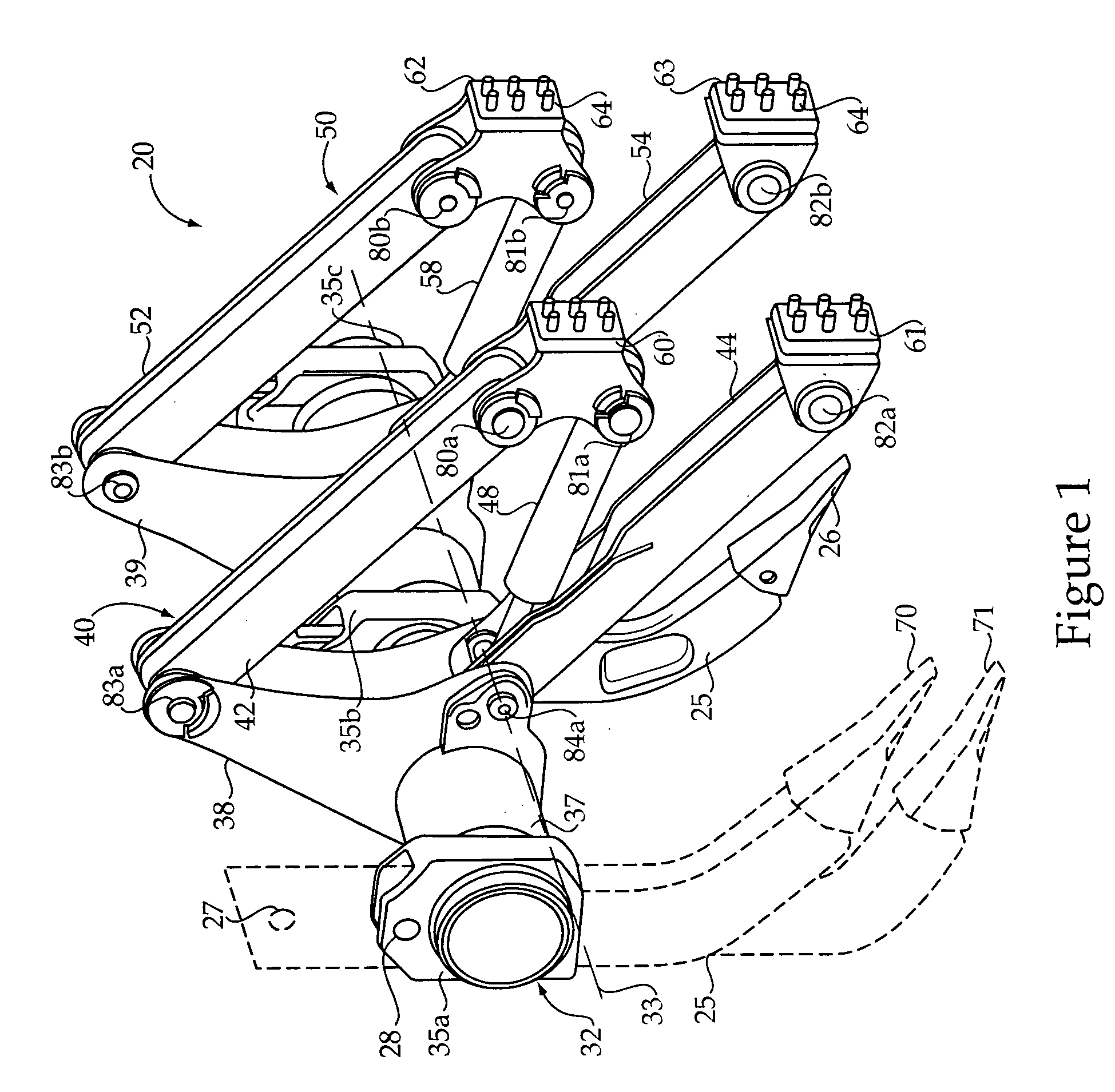
[0014]Referring to FIG. 1, a ripper assembly 20 includes a beam assembly 32 attached to a left linkage 40 and a right linkage 50. Left linkage 40 and right linkage 50 are illustrated as a fixed parallelogram, but the present disclosure also contemplates other ripper linkage configurations, including a variable parallelogram design and / or fixed or variable shapes that are other than a parallelogram. Left linkage 40 and right linkage 50 may be substantially identical to one another. Beam assembly 32 may include one or more elongate hollow cylinder beam members 37 shank mounts 35, and tower assemblies 38 and 39. Beam assembly 32 that is rotatable about a pin axis 33 when ripper assembly 20 is moved between raised and lowered positions. A central ripper shank 25 with a ripper tip 26 is attached to beam assembly at a centrally located shank mount 35b so as to be flanked by left linkage 40 and right linkage 50. Beam assembly 32 may include one or more a shank mounts 35 as is conventional ...


PUM


Abstract

A ripper assembly includes a beam assembly with a central ripper shank and tip flanked by a left linkage and a right linkage. In order to improve visibility of the central ripper shank and tip from an operator station of a track type tractor, the left linkage and the right linkage are unconnected to each other, except via the beam assembly. Without cross bracing between the left and right linkages, the beam assembly and individual linkages are configured to absorb side and twisting loads that may occur during production ripping. The ripper assembly left and right linkages may be of a fixed or variable parallelogram design. The hydraulic actuator(s) of the ripper assembly are configured to extend when moving to a dig position to provide a high penetration force. Part of the ripper assembly linkage shares a common pin with its associated hydraulic actuator. The ripper assembly may utilize a structurally efficient common pin shared between the beam assembly, lower link and hydraulic actuator on each side of the assembly.

Description

TECHNICAL FIELD[0001]The present disclosure relates generally to ripper assemblies, and more particularly to a ripper assembly configured to provide line of sight visibility from an operator station of a track type tractor to a central ripper shank and tip.BACKGROUND[0002]Production ripping has been used more and more today as an alternative to drilling and blasting with explosives. Current ripping strategies typically include mounting a ripper assembly with one or more ripper shanks on the back of a track type tractor or other machines known in the art. This arrangement, coupled with advanced hydraulic systems, more machine weight, and greater horsepower have greatly improved ripping performance and efficiency. A typical ripper assembly is based upon a parallelogram type linkage that may be lowered or raised to respective dig or raised stowed positions via one or more hydraulic actuators. In other ripper assemblies, an adjustable parallelogram permits adjusting an angle of attack o...

Claims


Application Information

Patent Timeline
IPC IPC(8): A01B63/102
CPCA01B13/08
Inventor JORGENSEN, JOHN E.MADDEN, BRIAN N.GROVE, ADAM C.ZIMMERMAN, WILLIAM H.
Owner CATERPILLAR INC
Why Eureka
Try Eureka