

Method and apparatus for detecting target parking position by using two reference points, and parking assist system using the same
- Summary
- Abstract
- Description
- Claims
- Application Information
AI Technical Summary
Benefits of technology
Problems solved by technology
Method used
Image

Examples
embodiment
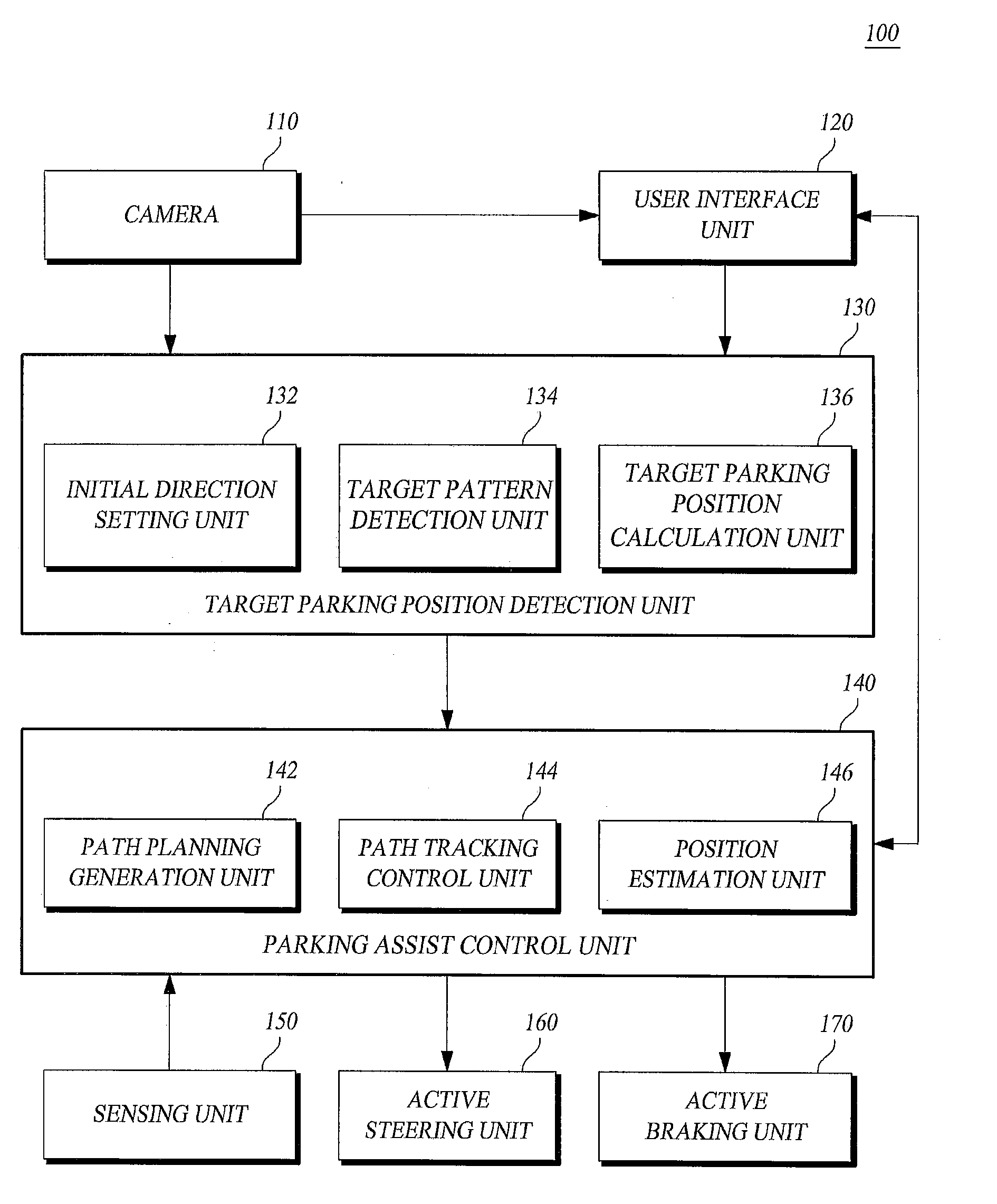
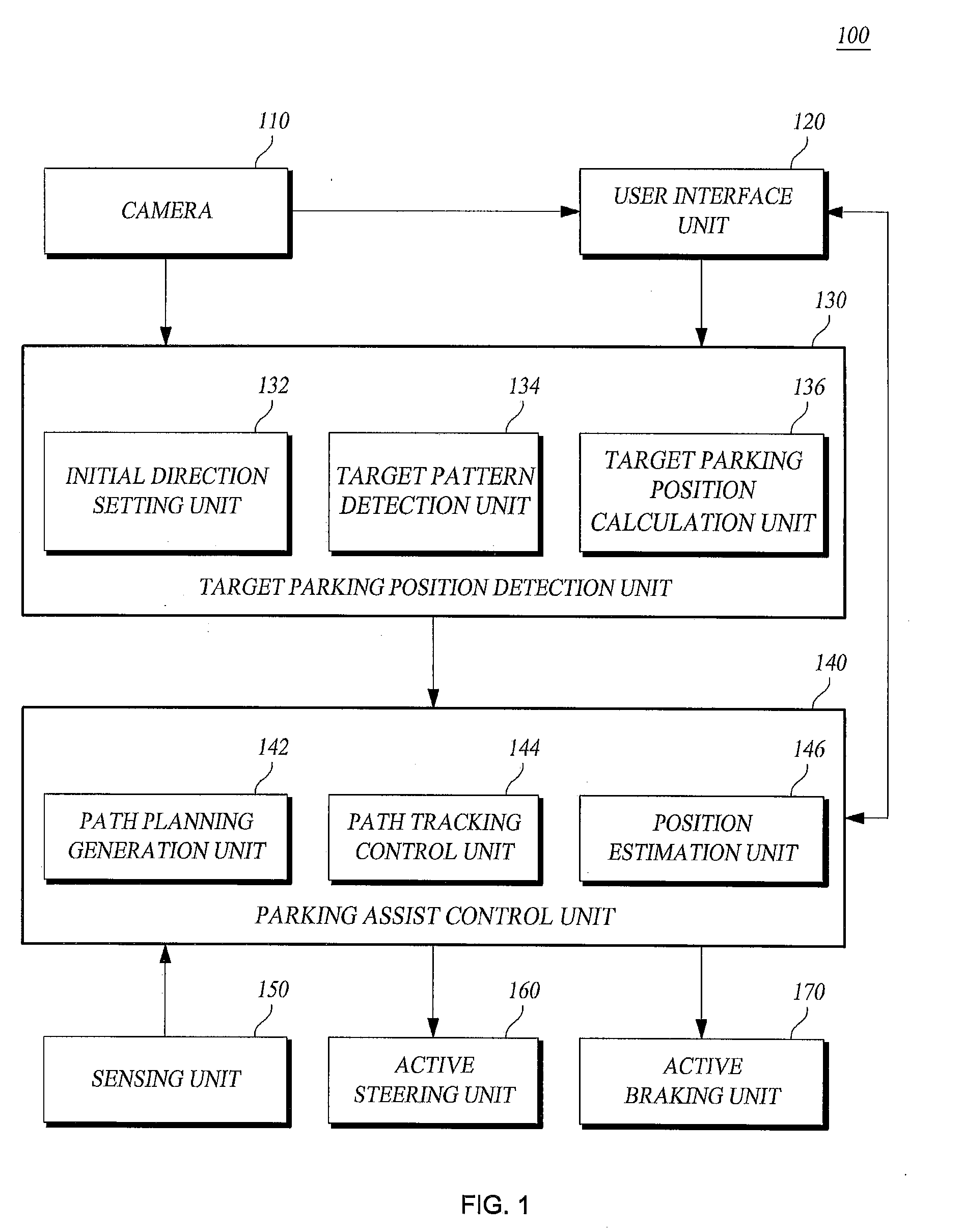
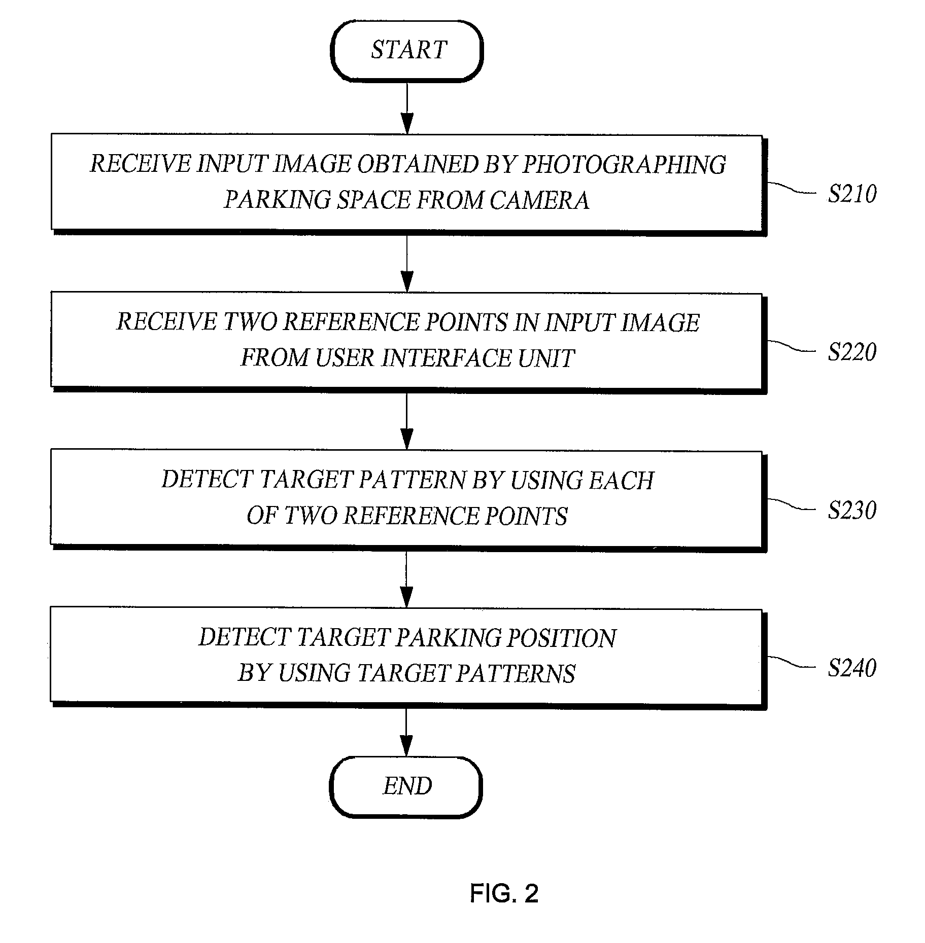
[0074]The apparatus for detecting a target parking position by using the two reference points according to an embodiment of the present invention uses a scheme in which the driver provides a hint for detecting the target parking position by using a touch-screen mounted in the vehicle.
[0075]Hereinafter, a description will be made of a case where the pattern of the parking slot markings is rectangular or 11-shaped. However, the idea of the art in the present invention is not necessarily applied to only the parking slot markings with these patterns. Even when the vehicle is parked in a parking lot whose parking slot markings have a pattern similar to any of the patterns as described above, the idea of the art in the present invention may be applied to the detection of a target parking position.
[0076]FIG. 4 is an illustrative view showing two reference points which are input in an input image.
[0077]Parking can be initiated when a driver changes the position of the gear to reverse. When ...
PUM
 Abstract
Description
Claims
Application Information