Reconfigurable multifrequency antenna with rf-mems switches

a multi-frequency antenna and rf-mems switch technology, applied in the direction of antennas, antenna feed intermediates, electrically short antennas, etc., can solve the problems of insufficient integration of rf-mems switches with antennas, unsatisfactory resolution of reconfigurable systems, and inability to meet the demand for reconfigurable systems,

Active Publication Date: 2009-08-20
STC UNM +1
View PDF3 Cites 50 Cited by
  • Summary
  • Abstract
  • Description
  • Claims
  • Application Information

AI Technical Summary

Benefits of technology

[0007]Accordingly, embodiments of the present invention are generally directed to a reconfigurable multifrequency self-similar planar antenna incorporating MEMS switches. In other words, the antenna is reconfigurable while maintaining similar patterns at different frequencies and radiates on demand at selected widely spaced frequencies.

Problems solved by technology

However, an increasing demand for reconfigurable systems, which are also versatile, has not yet been satisfactorily addressed.
An integration of RF-MEMS switches into known antenna systems has been attempted; however, an integration of RF-MEMS switches with the antenna has not been satisfactorily achieved.
Moreover, no multiband antenna has been shown or reported to be RF-MEMS reconfigurable.
In particular, there continue to be problems overcoming the effect of switch bias lines on the antenna performance.
The bias lines of the RF-MEMS switches have been found to problematically affect the radiation pattern of the antenna, as well as its resonant frequencies.
Furthermore, recovery from these problems can be difficult.
However, incorporation of these switches into an antenna configuration has not previously been successful because of the inability to bias them and place them in a way to not affect antenna performance.
Disadvantages include their long switching times (on the order of 1-20 μs), high actuation voltage and they are unable to handle high-power RF applications.

Method used


Image

  • Reconfigurable multifrequency antenna with rf-mems switches
  • Reconfigurable multifrequency antenna with rf-mems switches
  • Reconfigurable multifrequency antenna with rf-mems switches

Examples


Embodiment Construction

[0021]Reference will now be made in detail to exemplary embodiments of the invention, examples of which are illustrated in the accompanying drawings. Wherever possible, the same reference numbers will be used throughout the drawings to refer to the same or like parts.

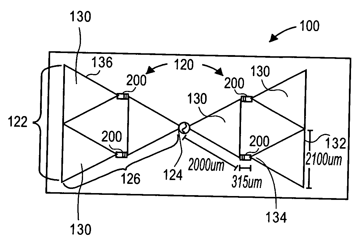
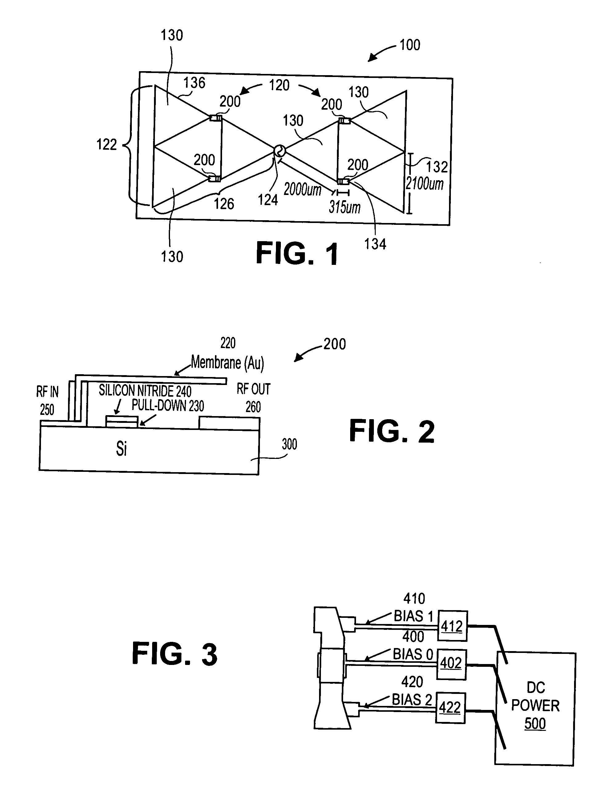
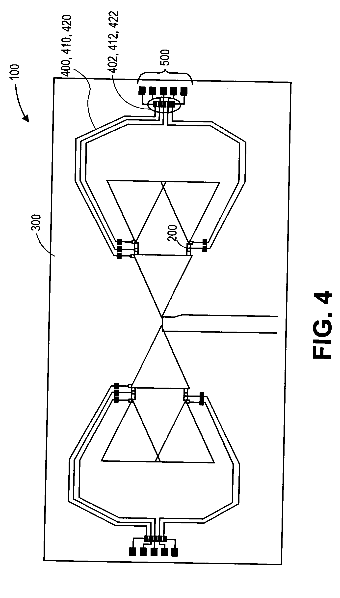
[0022]The following description of various exemplary embodiments including a self-similar fractal antenna configuration and a plurality of switches in a combination that yields a reconfigurable antenna that selectively radiates on demand at one of three different frequencies. The frequencies may be slightly varied according to a change in a bow-tie angle of the fractal antenna, but the length of each triangular patch is what affects the frequency the most.

[0023]The exemplary embodiments described herein are equally applicable to systems having more than one antenna iteration and various fractal self-similar configurations other than those described. In each instance, it will be appreciated that the outcome of a reconfig...


PUM


Abstract

A self-similar multiband reconfigurable antenna includes a planar antenna structure formed on a surface of a substrate, the antenna structure including symmetrically opposed self-similar geometry antenna arms defining a self-similar or Sierpinski gasket configuration for each arm of the antenna. MEMS type switches are provided for operatively connecting adjacent antenna patches on each arm of the antenna configuration, and a voltage source is provided for selectively actuating the switches. Selective actuation of the switches enables up to four different antenna configurations each having a different resonant frequency, and wherein each resonant frequency demonstrates a similar radiation pattern.

Description

CROSS-REFERENCE TO RELATED APPLICATIONS[0001]This application claims the benefit of U.S. Provisional Application No. 60 / 702,281 filed on Jul. 26, 2005, which is incorporated herein by reference in its entirety.FIELD OF THE INVENTION[0002]The present invention generally relates to a reconfigurable antenna, and, more particularly to a reconfigurable antenna incorporating a self-similar planar antenna and radio frequency micro-electromechanical (RF-MEMS) switches, the reconfigurable antenna radiating on demand at three frequencies.BACKGROUND OF THE INVENTION[0003]Modern communication systems demand multiband antenna performance. An apparatus to address this need is by using reconfigurable antennas. Reconfigurable antennas are known. However, an increasing demand for reconfigurable systems, which are also versatile, has not yet been satisfactorily addressed. In particular, there is a need to provide a reconfigurable antenna operable at multiple frequencies. At the present time, multiple...

Claims


Application Information

Patent Timeline
Patent Type & Authority Applications(United States)
IPC IPC(8): H01Q21/30
CPCH01Q9/285
Inventor ANAGNOSTOU, DIMITRIOSZHENG, GUIZHENPAPAPOLYMEROU, IOANNISCHRISTODOULOU, CHRISTOS
Owner STC UNM
Why Eureka
Try Eureka