Engine pylon made from composite material

Active Publication Date: 2009-08-27
SPIRIT AEROSYSTEMS
View PDF26 Cites 63 Cited by
  • Summary
  • Abstract
  • Description
  • Claims
  • Application Information

AI Technical Summary

Benefits of technology

[0012]The present invention provides an improved load-bearing structure, such as a pylon or strut, composed of composite material and metal fittings for supporting an engine on an airframe structure of an aircraft, such as a wing of the aircraft. The load-bearing structure design allows it to bear the load of the engine without requiring that the concentrated input loads bear up directly on the composi

Problems solved by technology

The aircraft industry has struggled to reduce the cost of this assembly while maintaining the highly redundant structure that assures this critical component will not fail despite its being located in an environment of high loading, high sonic fatigue, high temperatures, and corrosive gasses.
The use of these materials, instead of aluminum, raises the cost, both in the fabrication of the parts and in the assembly stage, where hundreds of holes must be drilled through these very tough materials.
Further, the use of mechanical fasteners requires considerable overlapping of the joining surfaces which adds weight and cost.
Composit

Method used


Image

  • Engine pylon made from composite material
  • Engine pylon made from composite material
  • Engine pylon made from composite material

Examples


Embodiment Construction

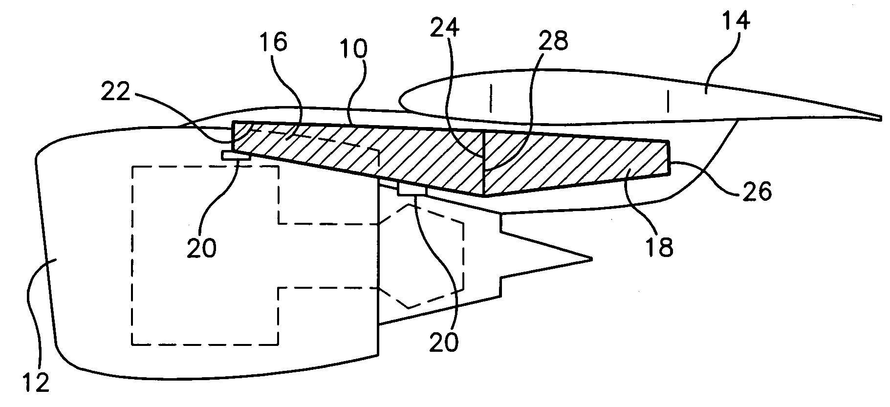
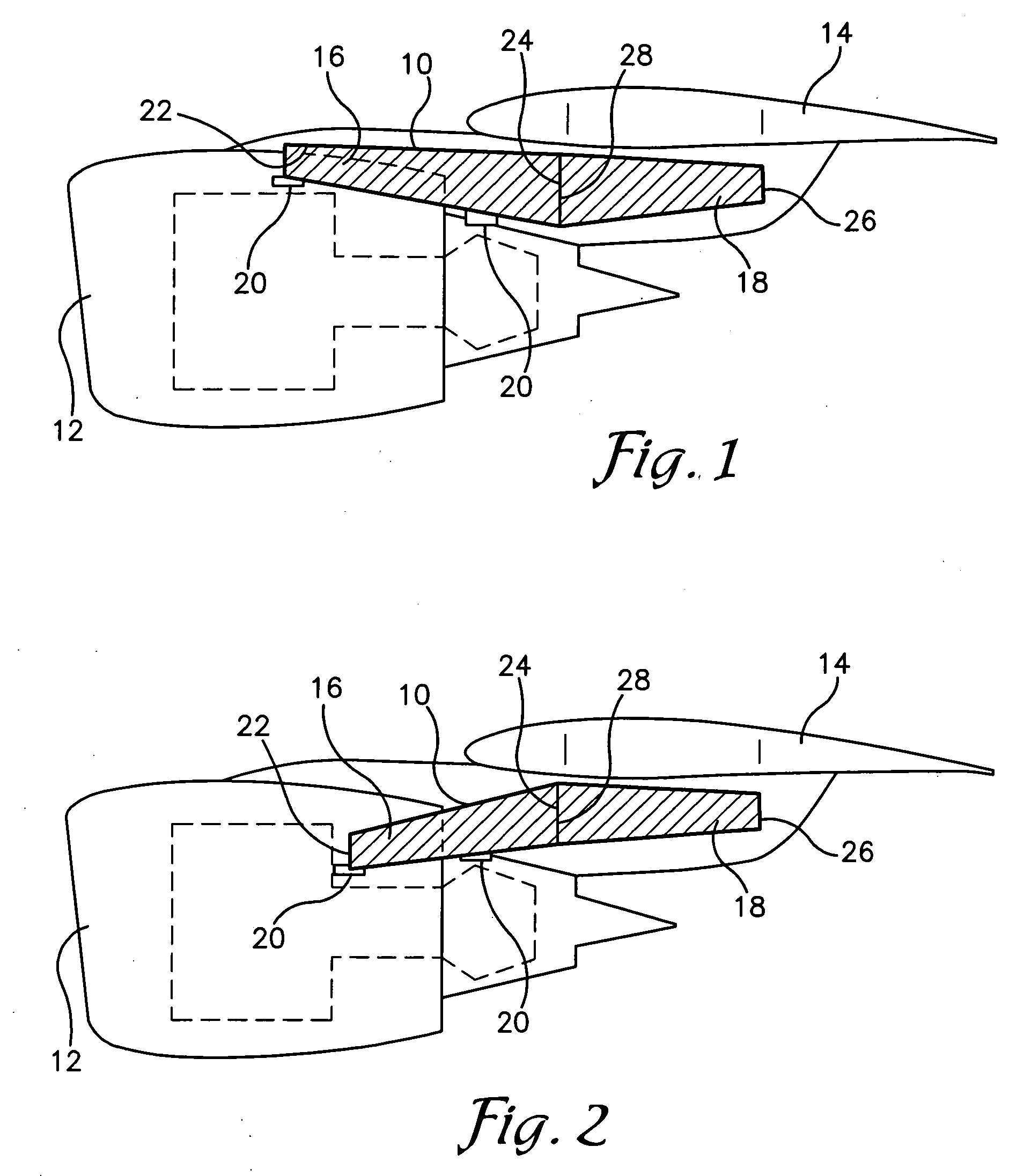
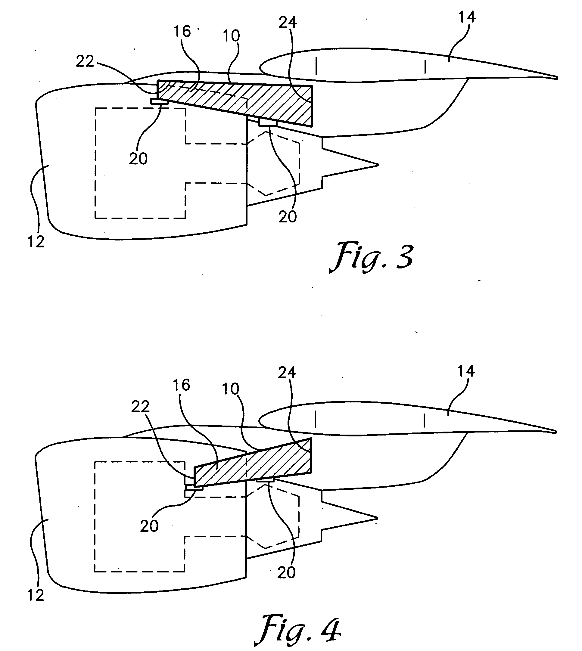
[0043]FIG. 1 illustrates a load-bearing structure 10, such as an aircraft pylon or a strut, constructed in accordance with an embodiment of the present invention. The load-bearing structure 10 may be used for supporting an engine 12 on an airframe structure of an aircraft, such as a wing 14 of the aircraft. Referring to FIG. 1, the load-bearing structure 10 comprises at least one of a first central structure 16 and a second central structure 18, both composed of composite material, and a plurality of fittings 20 operable to attach at least one of the first and second central structures 16,18 to the wing 14 and to attach at least one of the central structures 16,18 to the engine 12.

[0044]The first and second central structures 16,18 may be monolithic, substantially elongated tubular structures. As referenced herein, tubular refers to a substantially hollow body of any cross-sectional shape. The cross-section of the tubular central structures 16,18, as viewed from either end of the tu...


PUM


Abstract

A load-bearing structure, such as a pylon or strut, comprising a monolithic tubular-shaped first central structure composed of composite material and a plurality of metal fittings for supporting an engine on an airframe structure of an aircraft, such as a wing. Most of the fittings are integrated into the load-bearing structure through bonding. The metal fittings carry the high bearing loads that are transmitted into the pylon at the engine-pylon and wing-pylon interfaces. The load-bearing structure may also comprise a second central structure of a tubular shape composed of composite material and integrated with one end portion of the first central structure by bonding and/or mechanical fastening means.

Description

RELATED APPLICATION[0001]The present application is a nonprovisional patent application and claims priority benefit, with regard to all common subject matter, of earlier-filed U.S. provisional patent application titled, “Engine Pylon Made From Composite Material”, Ser. No. 61 / 031,883, filed Feb. 27, 2008, incorporated by reference into the present document.BACKGROUND[0002]1. Field[0003]The present invention relates to structural aircraft parts. More particularly, the present invention relates to a load-bearing structure, such as a pylon or a strut, for supporting an aircraft engine on an airframe structure of an aircraft.[0004]2. Related Art[0005]A pylon (or strut) that attaches a high-bypass engine to the wing of a commercial airliner is a complex structure that is very highly loaded and performs a multitude of functions such as supporting the engine weight, the fairings and systems, providing a fire and vapor barrier between the engine and the wing, transmitting the engine thrust ...

Claims


Application Information

Patent Timeline
IPC IPC(8): B64D27/26
CPCB64D27/26Y02T50/44B64D2027/264Y02T50/40
Inventor HUGGINS, GEORGE LARIMOREWEST, RANDALL RAYBRISCOE, RICHARD TODDWELCH, JOHN MICHAEL
Owner SPIRIT AEROSYSTEMS
Why Eureka
Try Eureka