Anti-collision Emergency Braking System

a technology of emergency brakes and anti-collision vehicles, applied in automatic initiation, transportation and packaging, instruments, etc., can solve the problems of significant delay for the driver to brake, the reaction process could be fatal, and the brake lights do not tell the trailing driver

Inactive Publication Date: 2009-08-27
LUO QI
View PDF11 Cites 24 Cited by
  • Summary
  • Abstract
  • Description
  • Claims
  • Application Information

AI Technical Summary

Benefits of technology

[0010]According to a preferred embodiment of the present invention, the anti-collision emergency braking system works while the driver of the present vehicle observes a danger situation and takes an emergency hard brake onto the brake pedal. At the time the driver takes the hard press to the brake pedal, the accelerometer will sense the deceleration extent. While the deceleration extent exceeds a pre-determined threshold, the accelerometer sends out an signal to the central commanding element, which will thereafter activate the transmitter which will then send out a series of radio frequency signals toward the rear direction, in the hope that the receiver of anti-collision emergency braking system in the trailing vehicle can receive these signals, so that the trailing vehicle and its driver can take proper actions accordingly.
[0015]In one embodiment of the present invention, the anti-collision emergency braking system has two functional coordinating elements, which are an electronically actuated back-locking element and a pressure sensor attached on the back-locking element. These two functional elements help the automatic braking element work harmonically with the regular foot-braking system.
[0016]In another embodiment of the present invention, the anti-collision emergency braking system may also have its central commanding system connected to a sensor on the gas pedal. While the driver depresses the gas pedal, this sensor senses the pressure on the gas pedal, then sends a signal to the central commanding element, and the central commanding element then sends a series of reset signals to the automatic braking element, the emergency warning light, the transmitter etc. This will bring the vehicle back to normal driving conditions.
[0020]In another embodiment of the present invention, the anti-collision emergency braking system may work both at high driving speed and at middle driving speed. It may have two settings for some of its functional elements, such as frequency, accelerometer, and its various sensors, and its central commanding element will take inputs of the current driving speed, and accordingly uses the correct settings for the involved functional elements, so that proper action can be taken.

Problems solved by technology

However, the braking lights do not tell the trailing driver whether this braking is just a normal speed adjustment or it is an emergency hard stop.
In an emergency situation, this reacting process could be fatal.
And, from time to time, drivers may be distracted away from the regular view field therefore may not perceive the warning signal at the earliest time.
Such situation may cause significant delay for the driver to brake.
In addition, during less than ideal weather conditions such as foggy, heavy snow, or raining, the braking signals may not be clear to the trailing drivers, and this will cause further delay of reaction.
The driver in a dangerous situation may not react in time, and as a result, the driver may not have enough time to bring his vehicle to a safe stop and run into a collision.

Method used


Image

  • Anti-collision Emergency Braking System
  • Anti-collision Emergency Braking System
  • Anti-collision Emergency Braking System

Examples


Embodiment Construction

[0024]The following detailed description is directed to certain specific embodiments with reference to the accompanying drawings, in which certain specific embodiments are shown. This invention may, however, be embodied in many different forms and should not be construed as limited to the embodiments set forth herein.

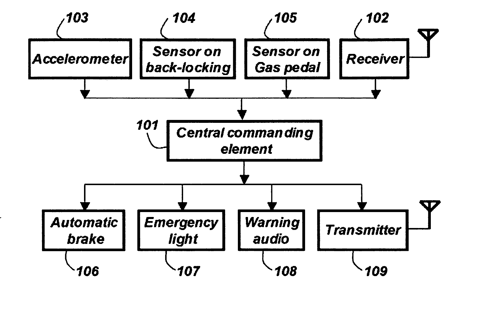
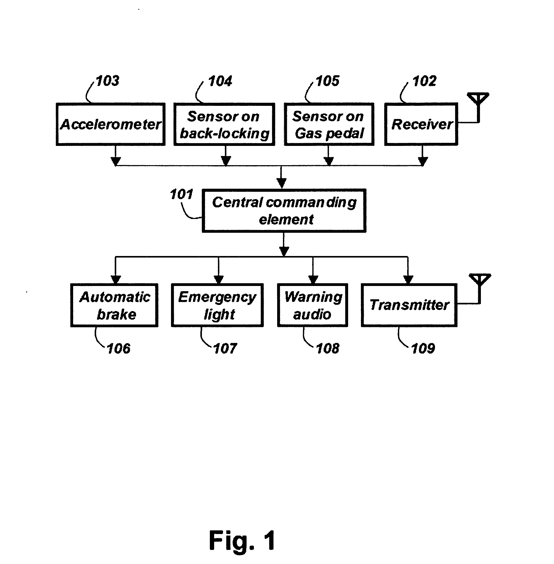
[0025]FIG. 1 is a flowchart illustrating the controlling logic of an anti-collision emergency braking system and its working mechanism. The core part of the system is a central commanding element 101. It takes input from four functional elements: a receiver 102, an accelerometer 103, a sensor on back-locking 104, and a sensor on gas pedal 105. Upon receiving the signals from these four functional elements, the central commanding element 101 will send out control signals to four other functional elements: an automatic brake 106, an emergency light 107, a warning audio 108 and a radio frequency transmitter 109. These four elements will be turned on or off depending on the...


PUM


Abstract

An anti-collision emergency braking system enables emergency information transferring from leading vehicle to trailing vehicle and enables emergency automatic braking. It comprises a central commanding element which takes input from a number of sensing elements and gives commands to other acting elements: a receiver which receives emergency signals from the leading vehicle, a transmitter which sends out emergency signals toward the trailing vehicle, an accelerometer which senses the acceleration extents of the present vehicle, an automatic braking element which applies certain amount of braking power after receiving the commands from the central commanding element, and one or more warning elements.

Description

FIELD OF THE INVENTION[0001]This invention relates to an anti-collision vehicle emergency braking system which enables automatic braking and emergency information transferring from leading to trailing vehicles. More particularly, the invention relates to a vehicle emergency braking system which includes functional elements of an accelerometer, a transmitter, a receiver, an automatic brake and its emergency warning elements.BACKGROUND OF THE INVENTION[0002]Most vehicles are equipped with braking lights in the rear windshield to warn a trailing driver that the leading vehicle's brake is being applied. The braking lights help to reduce the trailing driver's perception time that a braking action is taking place in the leading vehicle. However, the braking lights do not tell the trailing driver whether this braking is just a normal speed adjustment or it is an emergency hard stop. So, the trailing driver needs to observe how quick the leading vehicle is slowing down, and then make a judg...

Claims


Application Information

Patent Timeline
Patent Type & Authority Applications(United States)
IPC IPC(8): B60Q1/44
CPCB60Q1/444B60Q1/525G08G1/162B60Q2900/30B60T7/22B60Q9/008B60Q1/535
Inventor LUO, QI
Owner LUO QI
Why Eureka
Try Eureka