Evaluating pupillary responses to light stimuli

a technology of pupillary responses and light stimuli, applied in the field of evaluating pupillary responses to light stimuli, can solve the problems of lack of specificity for any one ocular disorder whether of neurological or transmissive origin, and magnitude less than 0.3 log units

Active Publication Date: 2009-08-27
KONAN MEDICAL USA
View PDF49 Cites 44 Cited by
  • Summary
  • Abstract
  • Description
  • Claims
  • Application Information

AI Technical Summary

Problems solved by technology

Generally, RAPDs of a magnitude less than 0.3 Log units are not measurable with this procedure, possibly owing the limitations of the examiner being able to observe small changes in pupil size of both eyes simultaneously.
However, the SFT has numerous drawbacks.
In particular, it lacks specificity for any one ocular disorder whether of neurological or transmissive origin.
Moreover, the SFT lacks sensitivity due to the manner in which the differences between the direct and consensual reflexes are observed.
The unaided observation makes this comparative judgment subject to significant error and makes the detection of small differences in reflexes between the two eyes especially problematic.
Because the SFT relies on the examiner's naked eye to detect and diagnose ocular dysfunctions, it lacks practical utility.
As a result, this manner of evoking the pupils' reflexes is lacking in both sensitivity and specificity.
First, patients with glauco...

Method used


Image

  • Evaluating pupillary responses to light stimuli
  • Evaluating pupillary responses to light stimuli
  • Evaluating pupillary responses to light stimuli

Examples


Embodiment Construction

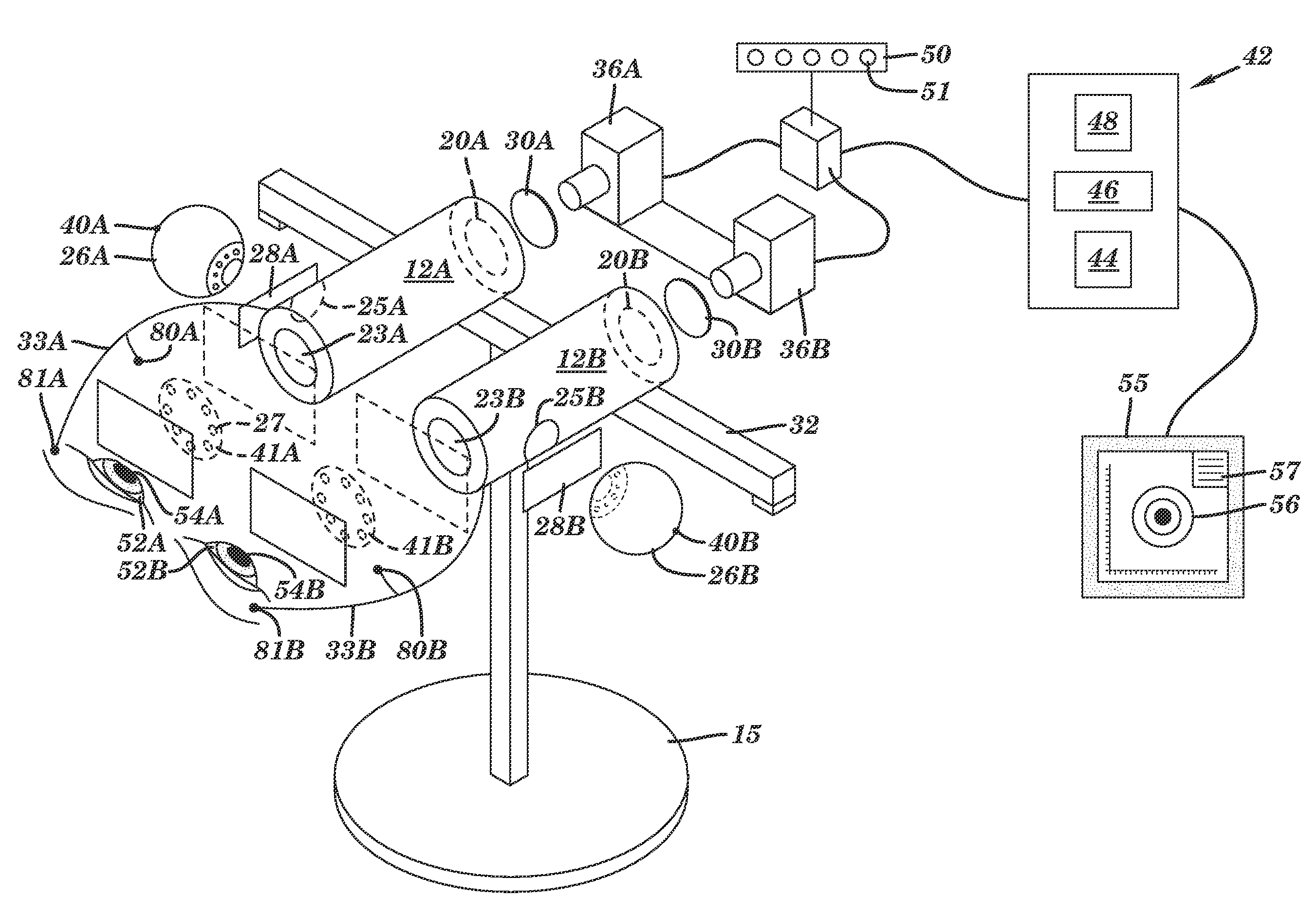
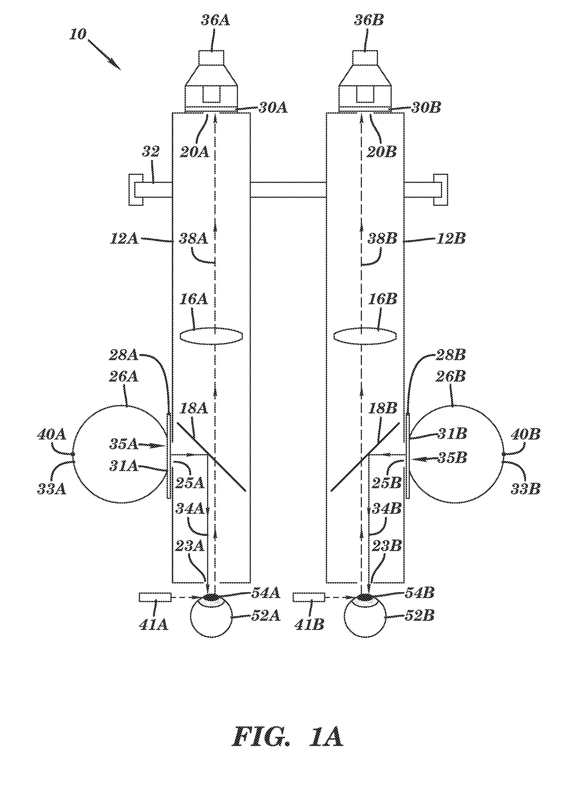
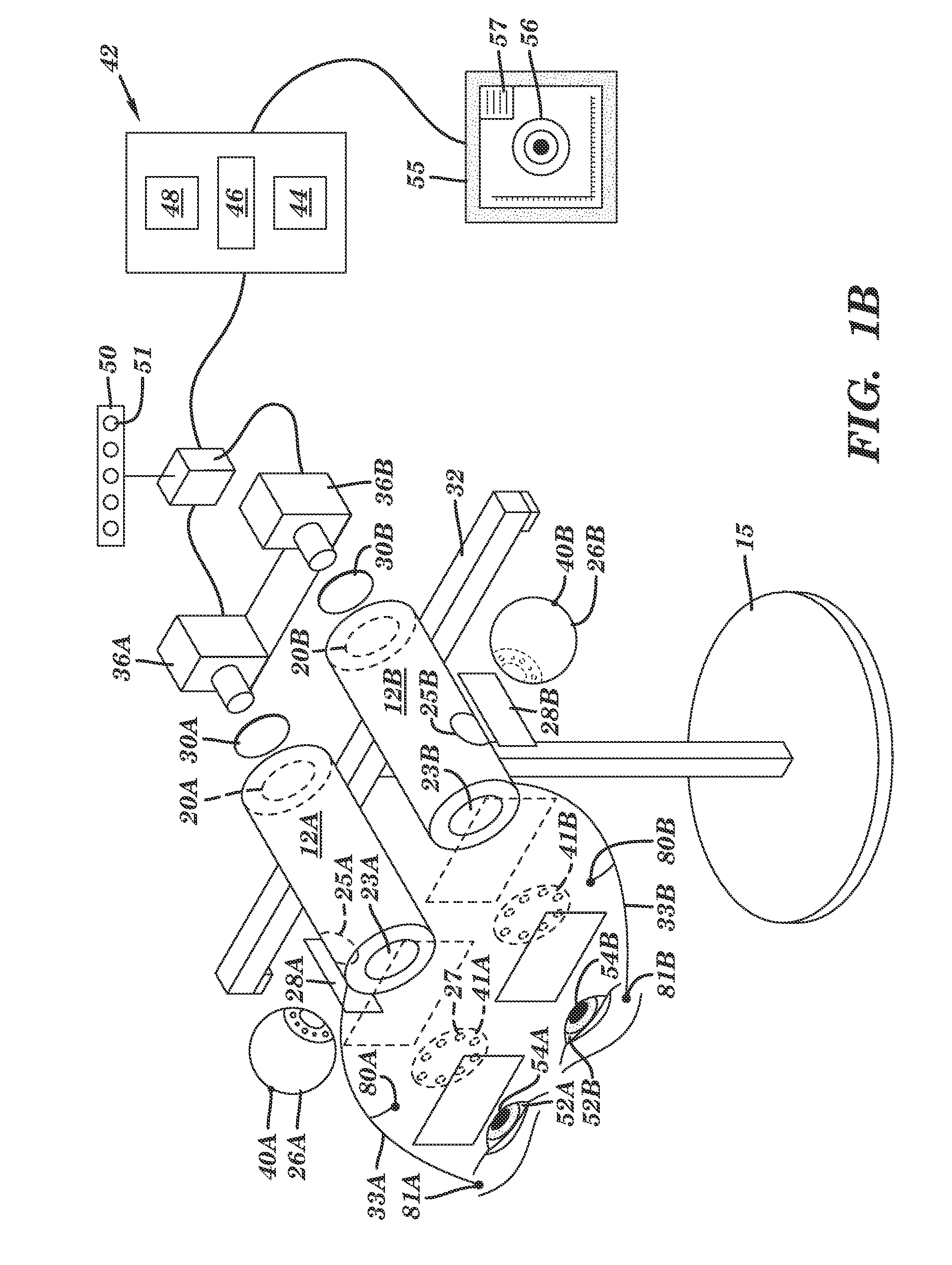
[0038]As stated above, the invention provides a solution for evaluating pupillary responses to light stimuli. The solution can include, for example, methods and / or systems that capture data about a patient's response to light stimuli. The solution can further include methods and / or systems that manipulate the captured data in order to evaluate the patient's response. In particular, a first eye is exposed to a series of flashes. Each flash can include substantially “white” light, or each flash can vary chromatically from the other flashes in the series. Pupillary reflexes for both eyes are measured during the exposures. The pupillary reflexes can be evaluated to determine if an ocular dysfunction is present. In one embodiment, both eyes are alternately exposed to the same series of flashes. Further, additional series of flashes that vary by location in the visual field and / or luminosity (i.e., brightness) can be incorporated and evaluated.

[0039]In an embodiment, the invention can tar...


PUM


Abstract

Solutions for evaluating the pupillary responses of a patient are disclosed. An illustrative method includes alternately exposing a first eye and a second eye of the patient to light stimulation in successive intervals, the light stimulation provided by at least one light source controlled by at least one computing device; concurrently capturing, with at least one image device controlled by the at least one computing device, image data of the first eye and the second eye during the exposing; and using the at least one computing device to perform the following: determine a center point of the first eye within the image data of the first eye and a center point of the second eye within the image data of the second eye; obtain image data of a first half of the first eye having an edge defined by a line of pixels intersecting the determined center point of the first eye; obtain image data of a second half of the second eye, the second half of the second eye opposing the first half of the first eye and having an edge defined by a line of pixels intersecting the determined center point of the second eye; create a composite image including the image data of the first half of the first eye and the image data of the second half of the second eye; and provide the composite image for evaluation.

Description

REFERENCE TO PRIOR APPLICATIONS[0001]The current application claims the benefit of co-pending U.S. Provisional Application No. 61 / 031,494, titled “Method, System and Device for Detecting Ocular Dysfunctions”, which was filed on 26 Feb. 2008, and U.S. Provisional Application No. 61 / 097,048, titled “Automated Swinging Flashlight Test”, which was filed on 15 Sep. 2008, both of which are hereby incorporated by reference.BACKGROUND OF THE INVENTION[0002]1. Technical Field[0003]The invention generally relates to a solution for evaluating pupillary responses to light stimuli. More particularly, the invention provides a solution for exposing one or both eyes to a series of light flashes and measuring the direct and / or consensual pupillary reflexes that can be used to detect the presence of various dysfunctions and / or disorders.[0004]2. Background Art[0005]During eye examinations, the pupillary reflexes of a patient are often monitored to determine the presence of various ocular dysfunctions...

Claims


Application Information

Patent Timeline
IPC IPC(8): A61B3/14
CPCA61B3/145A61B3/112
Inventor KANDEL, GILLRAY L.COHEN, AARON S.
Owner KONAN MEDICAL USA
Why Eureka
Try Eureka