Automatic rack loader

a rack loader and automatic technology, applied in the field of rack loaders, can solve the problems of difficult for a worker to keep a sausage completely straight, bending and sagging create unsightly blemishes in the collagen casing, and the method of sausage manufacturing is difficult to achiev

Inactive Publication Date: 2009-08-27
POLY CLIP SYST
View PDF28 Cites 10 Cited by
  • Summary
  • Abstract
  • Description
  • Claims
  • Application Information

AI Technical Summary

Problems solved by technology

Problems arise in this method of manufacture of sausages.
Accordingly, it is difficult for a worker to keep a sausage completely straight, as a worker who supports a, for example, three-foot-long sausage with two hands will often find the sausage bending or sagging in the middle.
Bending and sagging create unsightly blemishes in the collagen casing, displeasing to consumers.
Additionally, the manual nature of the operation means some percentage of sausages will be dropped and therefore ruined.
The manual nature of the operation also requires quite a bit of stooping and stretching by a worker, as the lowest tray of a rack is just inches off the floor and the highest level is often six feet off the floor.
Automated methods of accomplishing loading of sausages onto a rack are complicated by the orientation of the various parts of a sausage-making system.

Method used


Image

  • Automatic rack loader
  • Automatic rack loader
  • Automatic rack loader

Examples


first embodiment

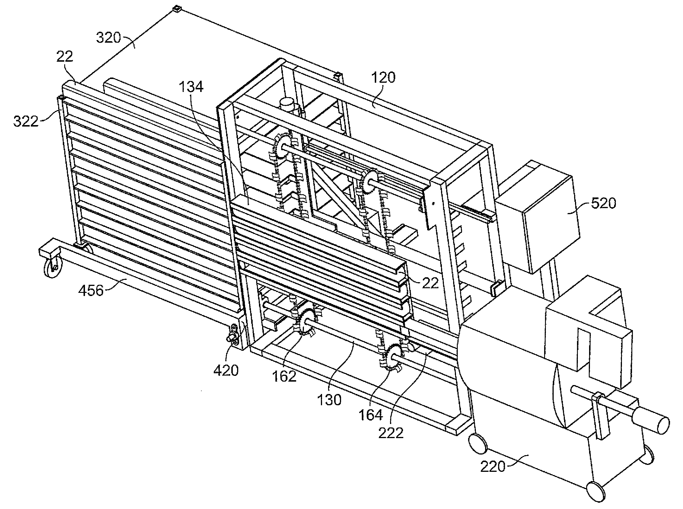
[0037]Rack positioner 420 is configured to move rack 320, placed adjacent the distal portion of frame 180 of automatic rack loader 120, in a direction perpendicular to rack loader 120. In a first embodiment, as illustrated in FIG. 6, rack 320 is placed on carriage 422, which moves on support 424. As illustrated, carriage 422 slides on rails 426, 428, but carriage 422 can move on a belt or chain conveyor, on wheels, or on any other system allowing carriage 422 to move in a direction perpendicular to the direction of movement of conveyor belt 222. Carriage 422 moves preferably by air-actuated cylinders 430, 432, but can also be moved by a belt drive, chain drive, screw drive, linkage to step motor, or other similar device.

second embodiment

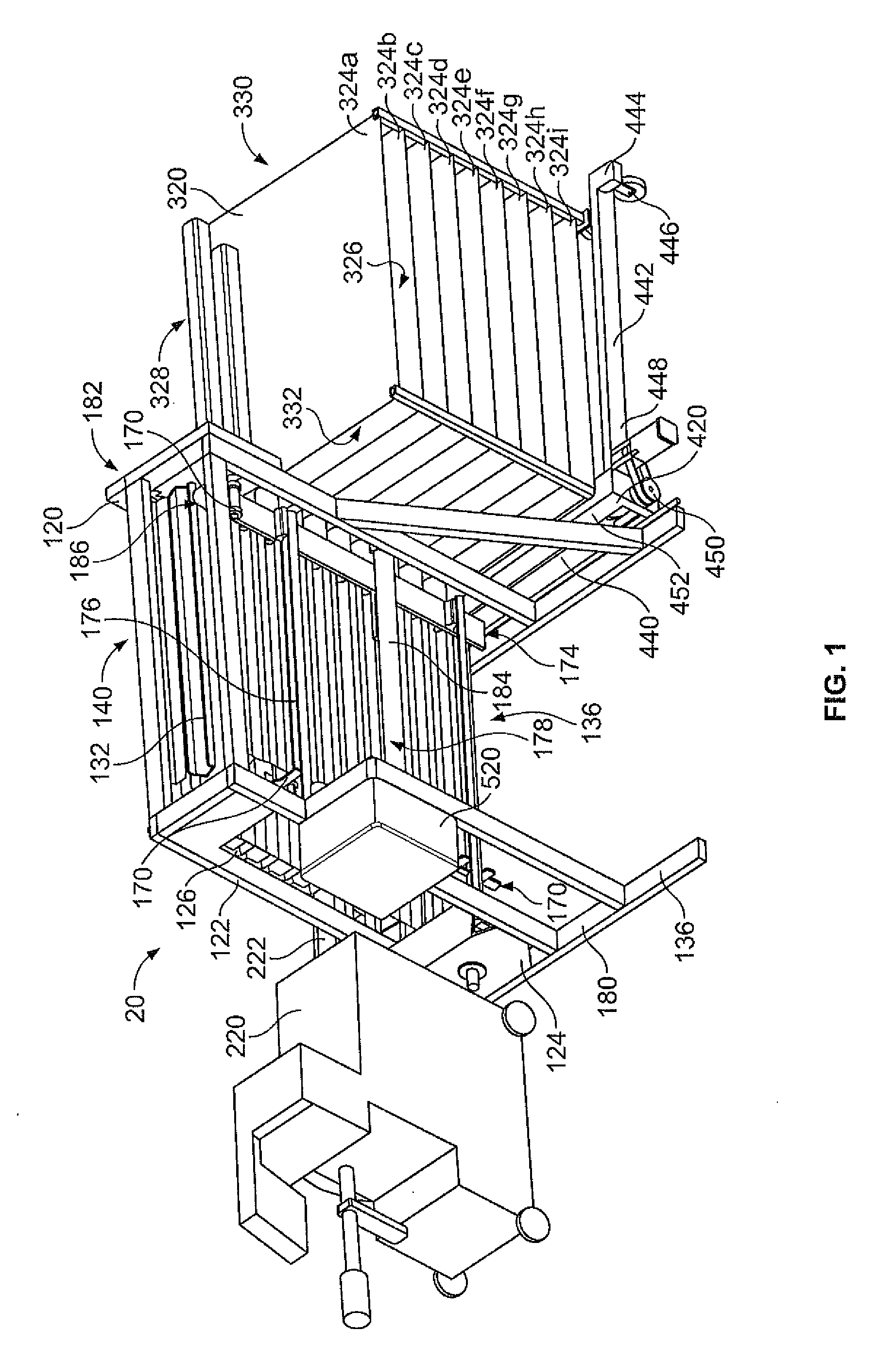
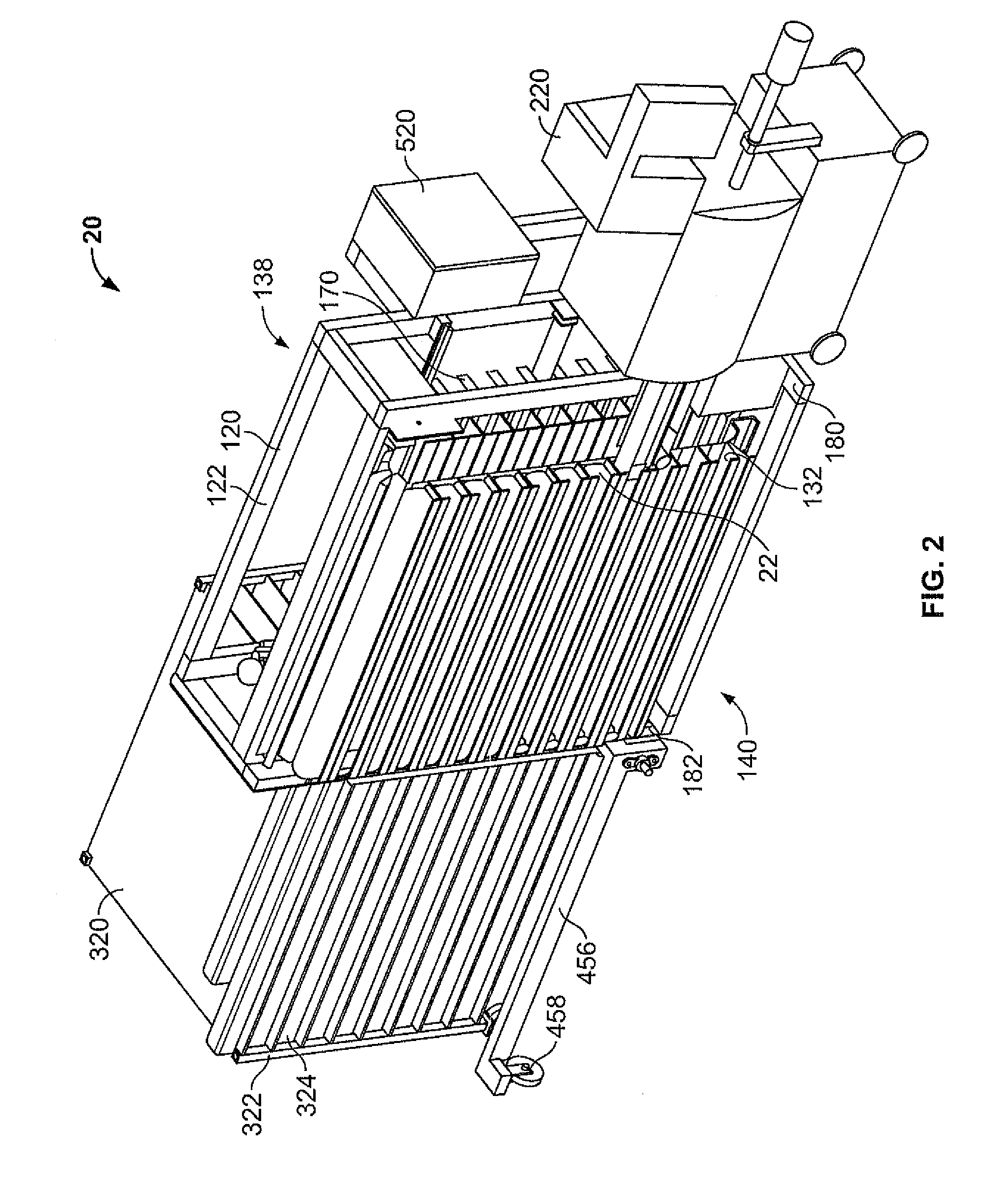
[0038]In a second embodiment, rack positioner 420 has a stop rail 440 positioned along the distal portion 182 of frame 122, a positioning rail 442 extending perpendicularly to stop rail 440 at the ride side 452 of stop rail 440, and a holding rail 456 extending perpendicularly from the left side 454 of stop rail 440, as shown in FIGS. 1 through 5. Positioning rail 442 is supported at its distal end 444 by wheel 446 and at its proximal end 448 by attachment to stop rail 440. A servo and screw drive 450, such as a THK ball screw made by Technico Inc., moves positioning rail 442 laterally from the right side 452 of stop rail 440 to the left side 454 of stop rail 440. Alternatively, a VFD gearmotor and Acme drive can be used. When a rack 320 is placed against stop rail 422 and positioning rail 442 is oriented alongside rack 320, movement of positioning rail from the right side 1452 toward the left side 454 will move rack 320 in the same direction. Holding rail 456, which is attached to ...


PUM


Abstract

An apparatus and system for loading items onto a rack is described. The rack loading apparatus is includes a stuffer / clipper for making sausages, a belt conveyor for receiving a sausage from the stuffer / clipper and conveying the sausage to a rotary conveyor, the rotary conveyor comprising a plurality of stages and having a loading side for receiving a sausage and an unloading side for discharging a sausage, a rack comprising a frame supporting a plurality of trays, a positioner to align the rack with the unloading side, a controller to cause the rotary conveyor to align a one of the plurality of stages on the loading side with the belt conveyor to receive a sausage from the stuffer / clipper and to rotate the rotary conveyor to align the one of the plurality of stages on the unloading side with a one of the plurality of trays, and a load pusher to discharge the sausage off the one of the plurality of stages and onto the one of the plurality of trays, the pusher comprising a plurality of tabs extending on a rotatable arm. In another embodiment, a rack loading apparatus for loading other manufactured items is described.

Description

PRIORITY[0001]This application is a division of U.S. patent application Ser. No. 11 / 252,327, filed Oct. 17, 2005, and also claims the benefit of U.S. Provisional Patent Application No. 60 / 696,005, filed on Jul. 1, 2005, the disclosures of both of which applications are incorporated herein by reference.BACKGROUND OF THE INVENTION[0002]This invention relates generally to the field of loading material onto racks. Specifically, this invention relates to loading sausages, whole-muscle meats such as hams, or other items onto racks for further processing, such as smoking or cooking. The invention will be described as used for sausages, but can be used for any items that are loaded onto a rack.[0003]Sausages are made by filling a casing with a pasty product in a tubular shape. The pasty product is usually a mixture of minced meat and seasonings, but can also be completely or partially made of vegetarian products. The pasty product is conveyed to a filler which pumps the pasty product throug...

Claims


Application Information

Patent Timeline
Patent Type & Authority Applications(United States)
IPC IPC(8): A22C11/00B65G1/10
CPCA22C11/008B65G2201/0202B65G65/00A22C15/007
Inventor HASCHKE, EGGO L.
Owner POLY CLIP SYST
Why Eureka
Try Eureka