Scanner and homing method of scanning module thereof

a scanning module and homing technology, applied in the field of scanning modules and homing methods of scanning modules thereof, can solve the problems of reducing the scanning quality of scanners, increasing the cost and complexity of manufacturing homing structures, and reducing the convenience of use, so as to improve the quality of scanning and reduce the cost and complexity of positioning plates

Inactive Publication Date: 2009-09-03
QUISDA CORP
View PDF3 Cites 4 Cited by
  • Summary
  • Abstract
  • Description
  • Claims
  • Application Information

AI Technical Summary

Benefits of technology

[0009]The invention is directed to a scanner and a homing method of a scanning module thereof. A positioning plate cooperates with a casing of the scanner to be used as a basis for homing the scanning module. Thus, the scanning module can be precisely homed, so that an image of a to-be-scanned document can be completely captured and the scanning quality is improved correspondingly. In addition, compared with a conventional homing structure, the positioning plate of the invention does not need to form any patterns thereon by a printing process. Therefore, the cost and complexity of the positioning plate of the invention in manufacturing are less than those of the conventional homing structure.

Problems solved by technology

However, the scanning module is not always precisely homed to the specific position, so that the scanning module may only capture a partial image of the document or even capture the image of other object.
Accordingly, the scanning quality of the scanner is reduced to lower the convenience in use.
However, as the black pattern 72 covers the white plate 71 by the printing process which is complicated and costly, the disposition of black pattern 72 usually increases the cost and complexity in manufacturing the homing structure 70.
Therefore, how to design a scanner capable of precisely homing to lower the cost and complexity in manufacturing and increase the scanning quality has become an imminent issue to the manufacturers.

Method used


Image

  • Scanner and homing method of scanning module thereof
  • Scanner and homing method of scanning module thereof
  • Scanner and homing method of scanning module thereof

Examples


Embodiment Construction

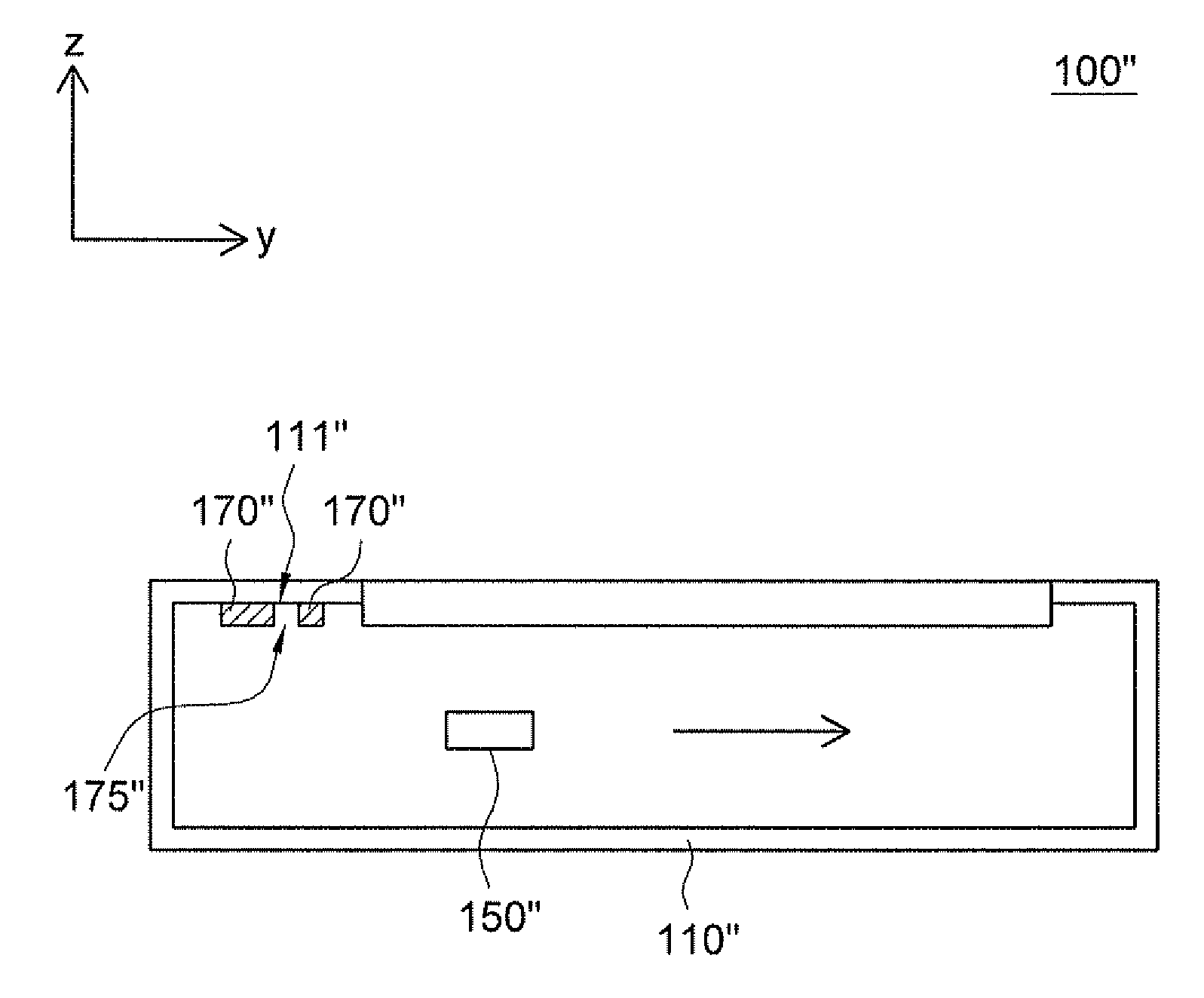
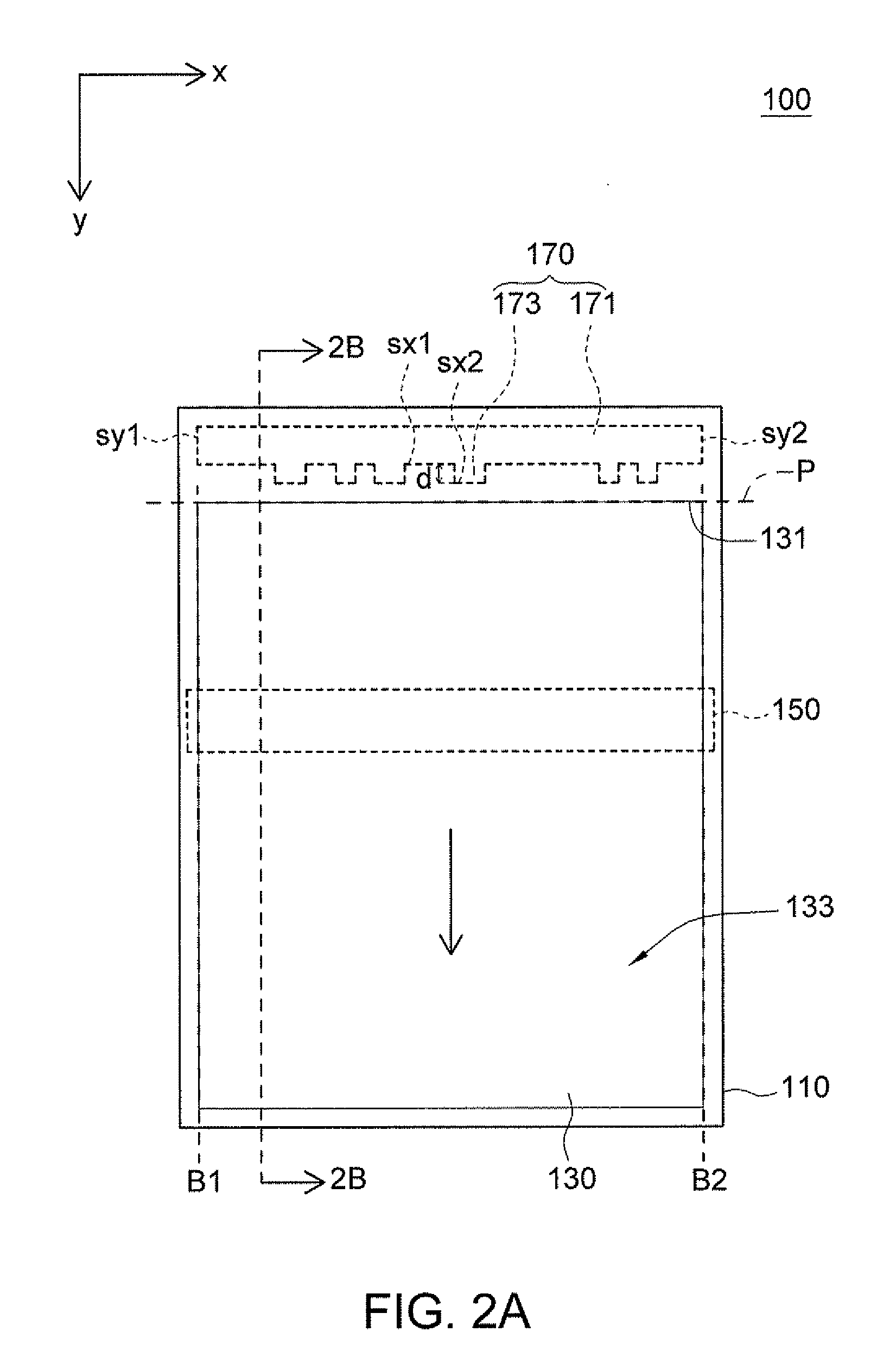
[0021]Referring to FIG. 2A and FIG. 2B, a top view of a scanner according to a preferred embodiment of the invention is shown in FIG. 2A, and a cross-sectional view of the scanner taken along line 2B-2B in FIG. 2A is shown in FIG. 2B. The scanner 100 includes a casing 110, a scanning platform 130, a scanning module 150 and a positioning plate 170. The scanning module 150 is, for example, a device including a charge-coupled device (CCD) or a device including a contact image sensor (CIS).

[0022]The scanning platform 130 is embedded in the casing 110 and exposes a surface 133 to carry a to-be-scanned document (not illustrated). The scanning platform 130 includes a top side 131. The scanning module 150 is disposed under the scanning platform 130. The positioning plate 170 is disposed on an inner wall 111 of the casing 110 and is adjacent to the top side 131 of the scanning platform 130. The scanning module 150 is used for capturing images of the positioning plate 170 and the inner wall 1...


PUM


Abstract

A scanner including a casing, a scanning platform, a scanning module and a positioning plate is provided. The scanning platform is embedded in the casing and exposes a surface to carry a to-be-scanned document. The scanning module is disposed under the scanning platform. The positioning plate disposed on an inner wall of the casing is adjacent to a top side of the scanning platform. The scanning module is for capturing images of the positioning plate and the inner wall and for identifying the image corresponding to one x-axis side of the positioning plate. The scanner defines a scanning start line according to the image corresponding to the x-axis side. The scanning module is moved from the scanning start line along a y-axis direction and captures an image of the to-be-scanned document. The x-axis side and the scanning start line are perpendicular to the y-axis direction perpendicular to the top side.

Description

[0001]This application claims the benefit of Taiwan application Serial No. 97107194, filed Feb. 29, 2008, the subject matter of which is incorporated herein by reference.BACKGROUND OF THE INVENTION[0002]1. Field of the Invention[0003]The invention relates in general to a scanner and a homing method of a scanning module thereof, and more particularly to a scanner capable of homing and a homing method of a scanning module thereof.[0004]2. Description of the Related Art[0005]Along with the rapid advance in technology, the scanner application has become popular. The scanner includes a scanning platform and a scanning module. The scanning module is disposed under the scanning platform. When a user would like to scan a document, the document is placed on the scanning platform. Then, the scanning module is moved along a direction to capture the image of the document.[0006]Generally speaking, the scanning module is homed to a specific position firstly before scanning begins so as to scan th...

Claims


Application Information

Patent Timeline
Patent Type & Authority Applications(United States)
IPC IPC(8): H04N1/047
CPCH04N1/00002H04N2201/0448H04N1/1017H04N1/00702
Inventor WENG, LI-KUIZHAN, XIAO-BING
Owner QUISDA CORP
Why Eureka
Try Eureka