Systems, assemblies and processes for controlling tools in a well bore

a technology of systems and assemblies, applied in the direction of wellbore/well accessories, fluid removal, earthwork drilling and mining, etc., can solve the problem of limiting the number of hydraulic lines the hanger can accommodate, the practical limit of the number of tools that can be controlled using the direct hydraulic arrangement is three, and the practical limit of the common close system is fiv

Inactive Publication Date: 2009-09-10
WEATHERFORD TECH HLDG LLC
View PDF102 Cites 113 Cited by
  • Summary
  • Abstract
  • Description
  • Claims
  • Application Information

AI Technical Summary

Benefits of technology

[0013]To achieve the foregoing and other objects, and in accordance with the purposes of the present invention, as embodied and broadly described herein, one characterization of the present invention is a hydraulic control system for use in a subterranean well is provided. The control system comprises a control line positioned in a subterranean well and extending adjacent at least one tool positioned within the subterranean well. The control line is sized to permit passage of a control device and each of the at least one tool has a reader device connected thereto.

Problems solved by technology

The practical limit to the number of tools that can be controlled using the direct hydraulic arrangement is three, i.e. six separate hydraulic lines, due to the physical restraints in positioning hydraulic lines in a well.
The tubing hanger through which the hydraulic lines run also has to accommodate lines for a gauge system, at least one safety valve and often a chemical injection line, which limits the number of hydraulic lines the hanger can accommodate.
Again, the common close system has a practical limit of controlling five tools, i.e. six separate hydraulic lines.
The controllers employed in the single line and the digital hydraulics arrangements are complex devices incorporating numerous elastomeric seals and springs which are subject to failure.
These filters are prone to clogging and collapsing.
Further, the complex nature of the pressure sequences requires a computer operated pump and valve manifold which is expensive.
This arrangement is expensive due to the large number of components and complex arrangement of seals in the controller and unreliable as it is difficult to get feedback to the surface on the exact position of the controller, especially if the operator has lost track of the pulses previously applied.
However, problems exist with hydraulically fracturing subterranean environs from multiple, spaced apart locations in sequence beginning with location that is farthest from the surface along the well bore.
This can cause hydraulic fractures formed in the adjacent region to propagate away from the previously fractured region which may not be desirable.

Method used


Image

  • Systems, assemblies and processes for controlling tools in a well bore
  • Systems, assemblies and processes for controlling tools in a well bore
  • Systems, assemblies and processes for controlling tools in a well bore

Examples


example 1

[0052]A well is drilled to total depth (TD) so as to penetrate a subterranean formation of interest and the drilling assembly is removed from the well. A 7 inch outer diameter intermediate casing is positioned in the well to extend substantially from the surface of the earth to a point above the subterranean formation of interest. The intermediate casing is cemented to the well bore by circulating cement. Excess cement is drilled from the intermediate casing and well bore extending below the intermediate casing through the subterranean zone of interest.

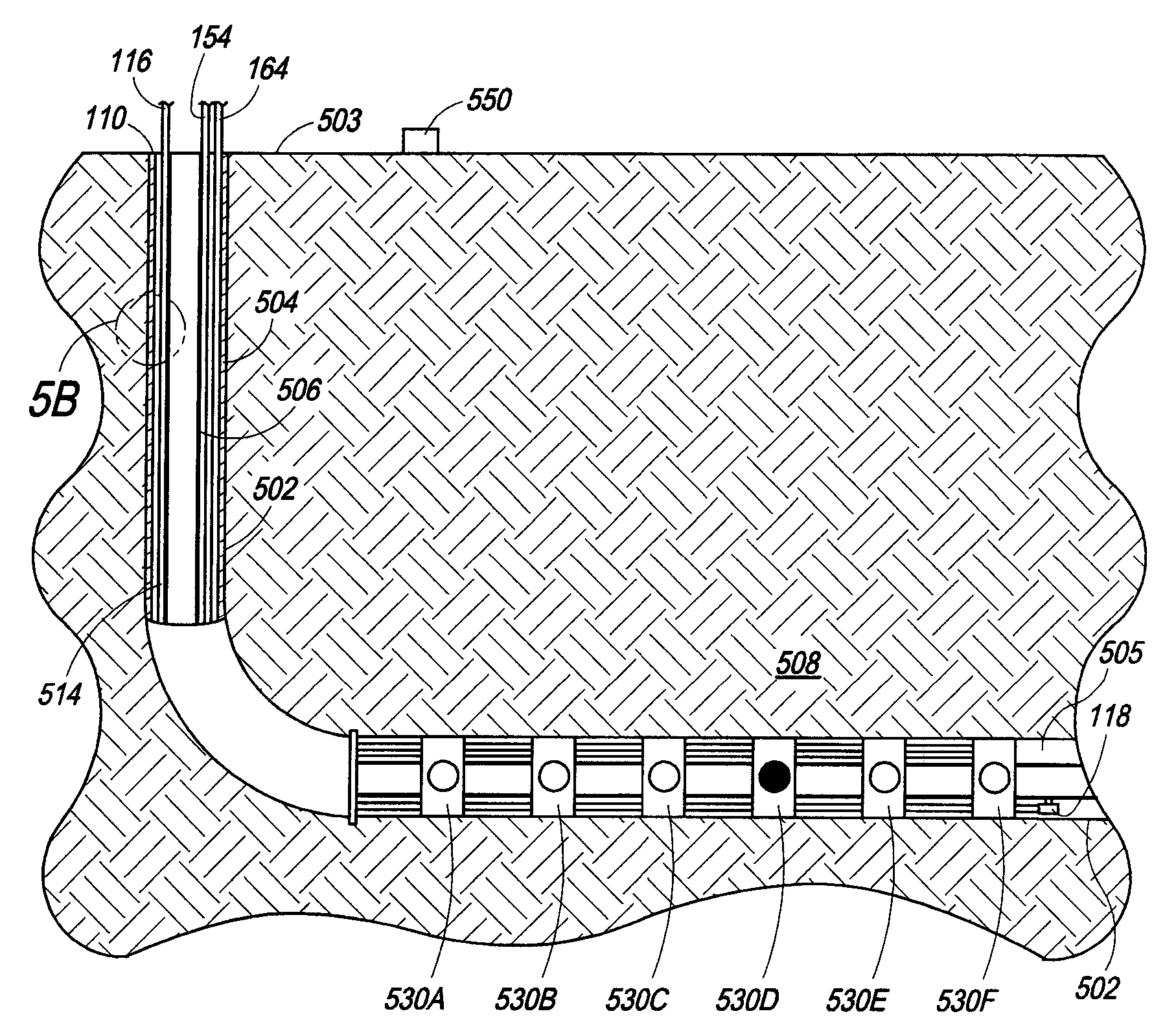
[0053]A 3.5 inch outer diameter production casing is equipped with 6 sliding sleeves and has 3 hydraulic lines attached to the outside of the production casing. The sliding sleeves are arranged in series and referred to hereafter as sliding sleeves 1-6, with sliding sleeve 1 being proximal and sliding sleeve 6 being distal the intermediate casing. The hydraulic lines are a control line, a hydraulic power open line and a hydraulic powe...


PUM


Abstract

A dedicated hydraulic line for transmission of a signal device capable of generating one or more unique signals to one or more tools within a subterranean well. Each tool can be equipped with a reader device for receiving signals from and transmitting signals to the signal device. Each reader device can control operation of the tool associated therewith if the reader device is programmed to respond to signals received from the control device. Hydraulic fluid used to operate the tool can be conveyed via the dedicated hydraulic line or a separate hydraulic line. A separate hydraulic line can be used to reset the tool. Where the tools include sliding sleeves, the tools can be used to hydraulically fracture subterranean environs at spaced apart locations along a well bore in any desired sequence and without removing the tools from the well during the fracturing process.

Description

REFERENCE TO RELATED PATENT APPLICATION:[0001]This application is a continuation-in-part of copending U.S. patent application Ser. No. 12 / 044,087 filed on Mar. 7, 2008 and entitled “Systems, Assemblies and Processes for Controlling Tools in a Well Bore”.BACKGROUND OF THE INVENTION[0002]1. Field of the Invention[0003]The present invention relates to systems, assemblies and processes for controlling equipment, tools and the like that are positioned in a subterranean well bore, and more particularly, to systems, assemblies and processes for controlling a plurality of equipment, tools and the like that are positioned in a subterranean well bore.[0004]2. Description of Related Art[0005]In the production of fluid from subterranean environs, a well bore is drilled so as to penetrate one or more subterranean zone(s), horizon(s) and / or formation(s). The well is typically completed by positioning casing which can be made up of tubular joints into the well bore and securing the casing therein ...

Claims


Application Information

Patent Timeline
Patent Type & Authority Applications(United States)
IPC IPC(8): E21B43/26
CPCE21B23/00E21B43/26E21B43/14E21B34/16
Inventor SNIDER, PHILIP M.
Owner WEATHERFORD TECH HLDG LLC
Why Eureka
Try Eureka