Magnetic tape device

Inactive Publication Date: 2009-09-10
NEC PERSONAL PRODUCTS LTD
View PDF3 Cites 5 Cited by
  • Summary
  • Abstract
  • Description
  • Claims
  • Application Information

AI Technical Summary

Benefits of technology

[0016]The present invention provides an advantageous effect that the operation to eliminate the sticking of the magnetic tape

Problems solved by technology

Therefore, if the reference temperature is set too low, the operation to eliminate the sticking of the magnetic tape to the magnetic head is performed even though the magnetic tape is not stuck to the magnetic head, posing a problem that the operation to eliminate the sticking is performed too often.
If the reference temperature is set too high, in contrast, it takes some time to commence the operation to eliminate the st

Method used


Image

  • Magnetic tape device
  • Magnetic tape device
  • Magnetic tape device

Examples


Example

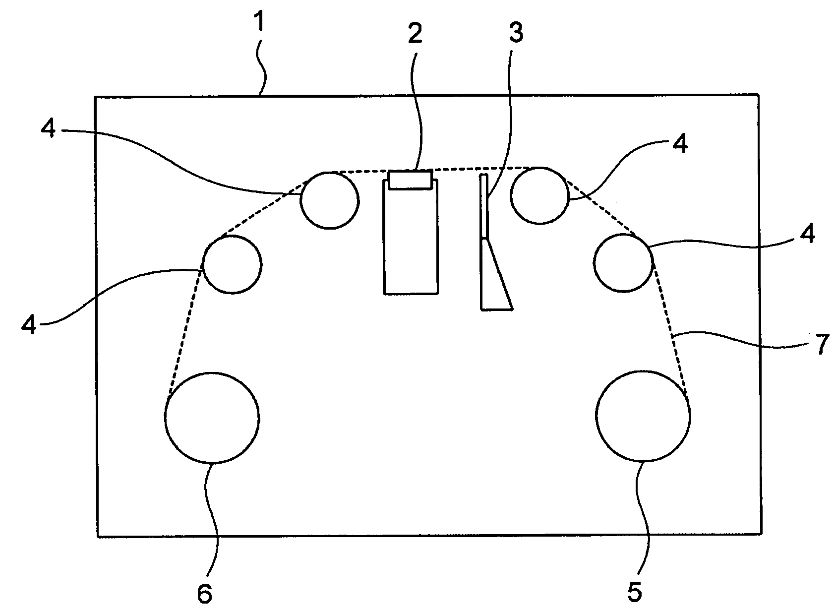
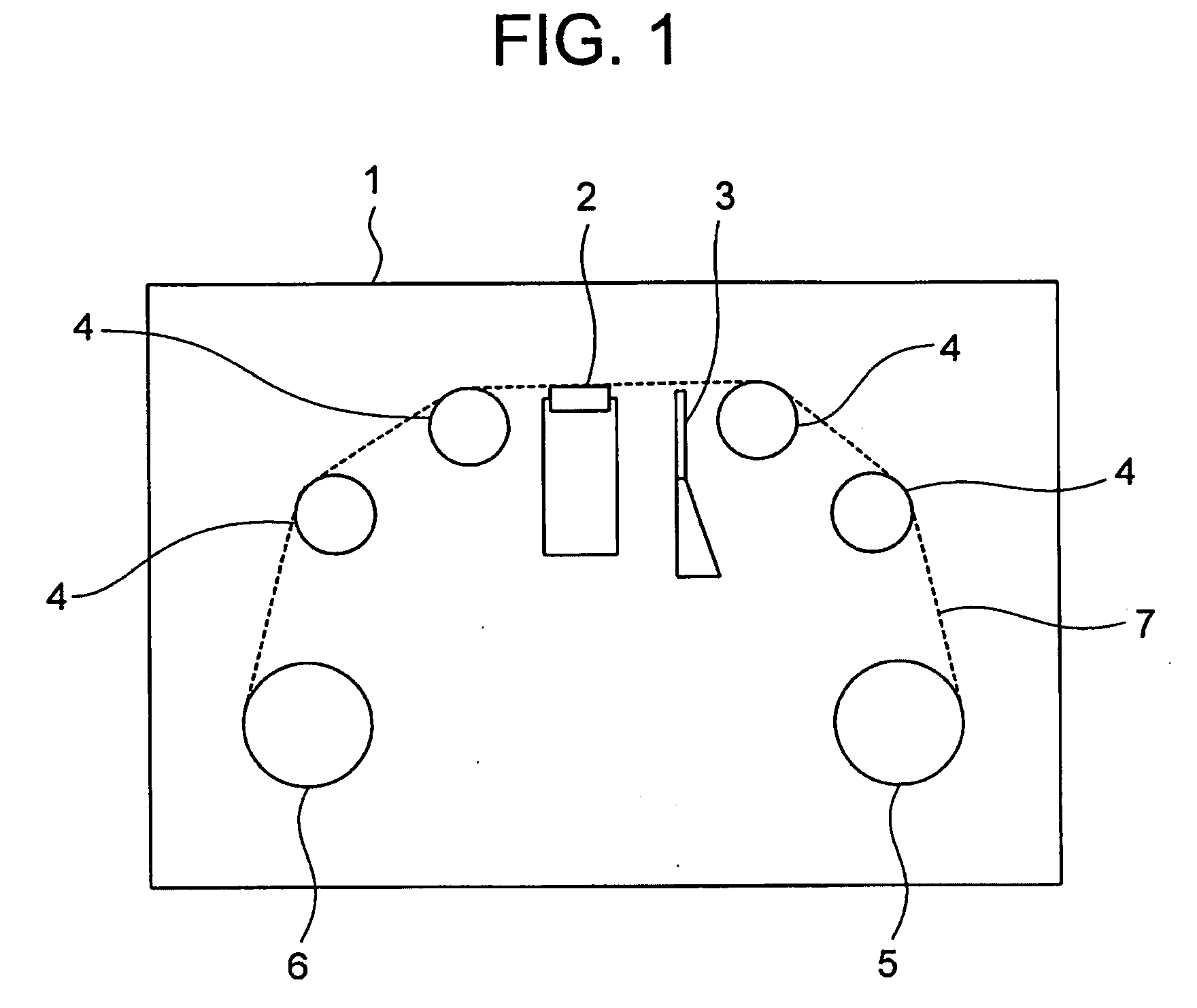
[0023]A most preferred exemplary embodiment will be described with reference to the accompanying drawings. FIG. 1 is a plan view illustrating a principal portion of a magnetic tape device according to an embodiment of the present invention. As shown in FIG. 1, the magnetic tape device 1 comprises a magnetic head 2, a tape lifter 3, a roller guide 4, a cartridge reel 5, a machine reel flange 6, and magnetic tape 7.

[0024]Next, description will be made of how the magnetic tape 7 is run within the magnetic tape device. In the state of the magnetic tape 7 as shown in FIG. 1, an end of the magnetic tape 7 stored on the cartridge reel 5 is in contact with the roller guide 4 and the magnetic head 2, and is connected to a certain part of the machine reel flange 6.

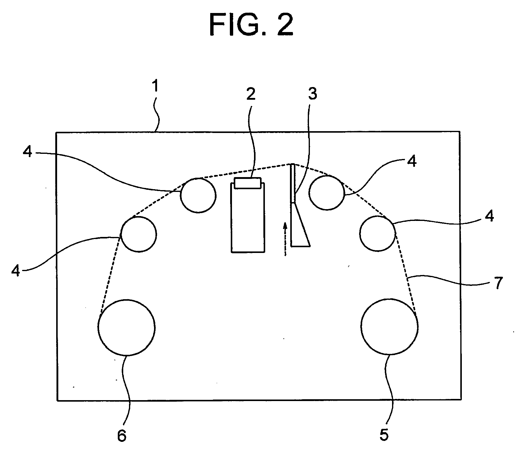
[0025]The cartridge reel 5 and the machine reel flange 6 are driven separately by a reel motor 8 (not shown in FIG. 1) which is an independent drive unit. Thus, the magnetic tape 7 can be run under a certain tension by driving the i...


PUM


Abstract

The invention provides a magnetic tape device including a magnetic head; a drive unit; an abnormality detector for detecting an abnormality in operation of the magnetic tape; and a release unit for releasing the contact between the magnetic tape and the magnetic head when the abnormality detector detects any abnormality during the running of the magnetic tape.

Description

[0001]This application is based upon and claims the benefit of priority from Japanese patent application No. 2008-052764, filed Mar. 4, 2008, the disclosure of which is incorporated herein in its entirety by reference.BACKGROUND OF THE INVENTION[0002]1. Field of the Invention[0003]The present invention relates to a magnetic tape device for recording and reproducing data on magnetic tape.[0004]2. Background of the Invention[0005]Magnetic tape devices employing magnetic tape as a storage medium have recently been developed as external storage devices for computers. When a magnetic tape device performs data recording or reproduction processing, magnetic tape runs in contact with a magnetic head. When the recording or reproduction processing is suspended, the magnetic tape remains in contact with the magnetic head. If the magnetic tape stays in this state for a prolonged time, the magnetic tape is possibly stuck on the magnetic head. Therefore, there are demands for countermeasures agai...

Claims


Application Information

Patent Timeline
IPC IPC(8): G11B27/36G11B5/78
CPCG11B15/026G11B15/62G11B15/18
Inventor OJIMA, KENICHI
Owner NEC PERSONAL PRODUCTS LTD
Why Eureka
Try Eureka