Device hoding structure

a technology for hoisting devices and devices, which is applied in the direction of traveller's bags, travel articles, bracelets, etc., can solve the problems of delay in viewing or checking the current time, at the very least frustrating the “adjusting process” and can be difficult, at the very least frustrating

Inactive Publication Date: 2009-09-17
DEVERS BROCK L
View PDF28 Cites 3 Cited by
  • Summary
  • Abstract
  • Description
  • Claims
  • Application Information

AI Technical Summary

Problems solved by technology

This “adjusting process” is at the very least frustrating and can be difficult when for example, the wearer does not have a free hand available to adjust or rotate the wrist band.
Consequently, the wearer is required to slide the sleeve portion upwardly until the sleeve no longer conceals.
Again, this can be frustrating at the very least.
Also both examples given causes delay in viewing or checking the current time.

Method used


Image

  • Device hoding structure
  • Device hoding structure
  • Device hoding structure

Examples


Embodiment Construction

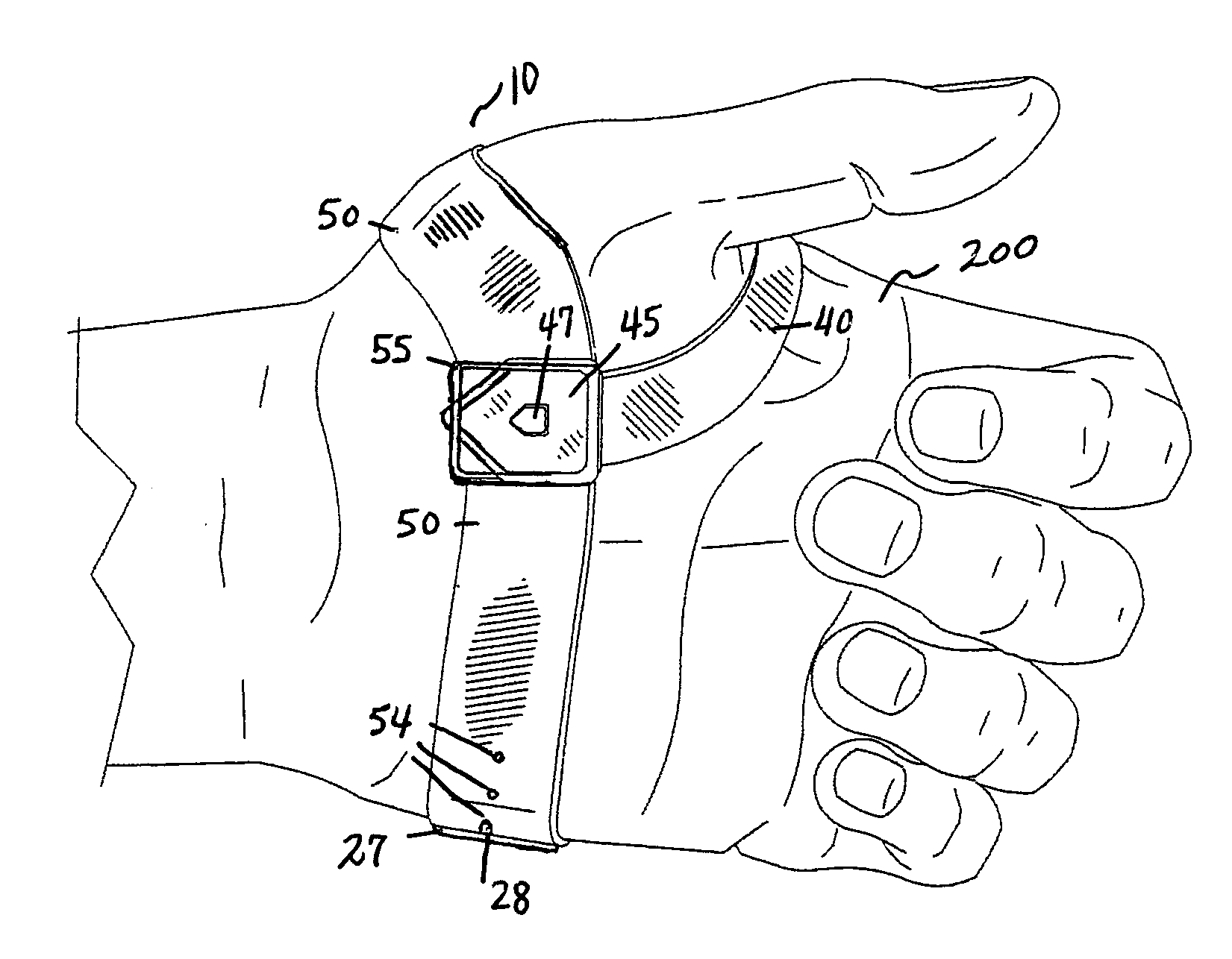
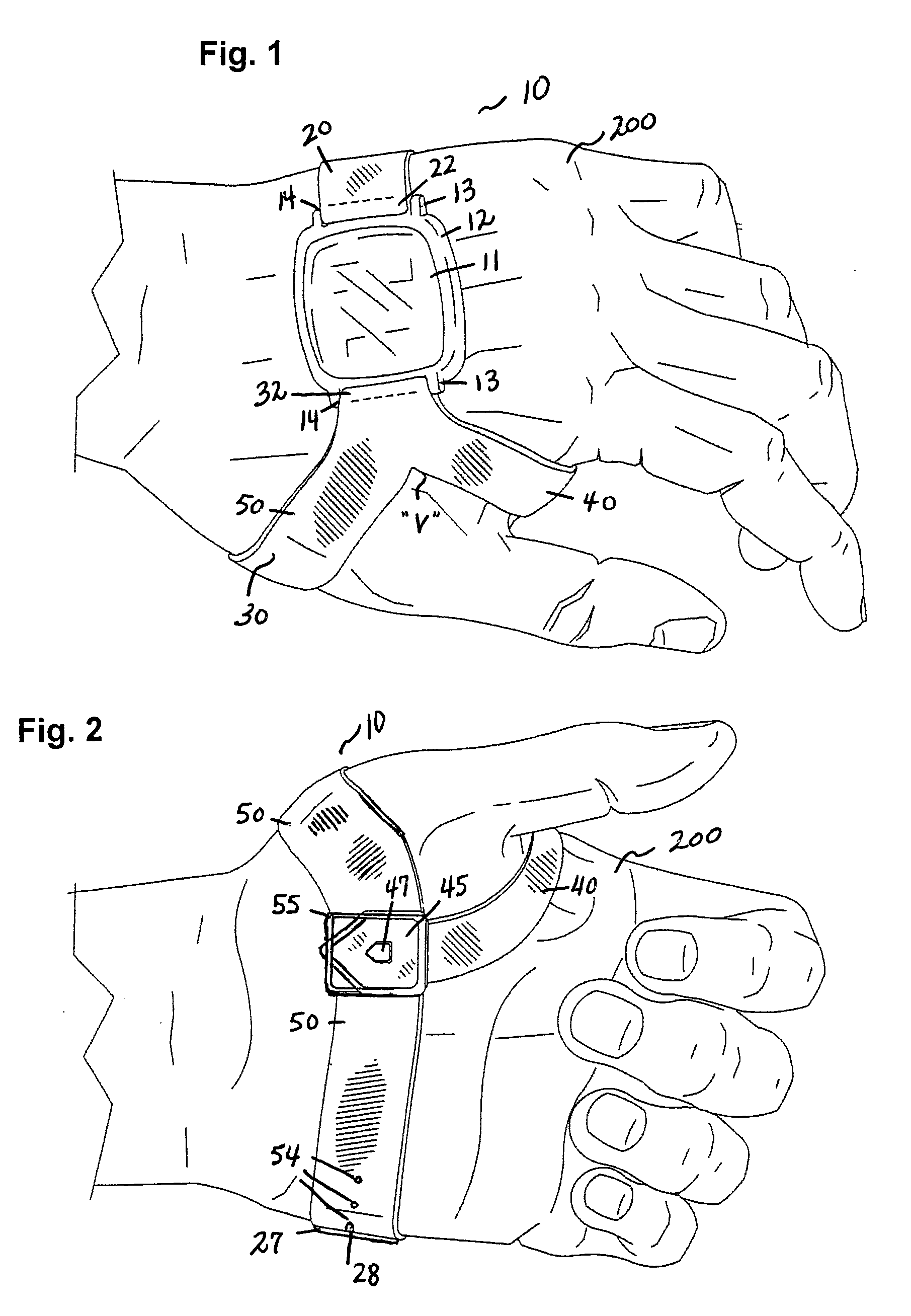
[0018]In accordance with the present invention, a device holding structure is disclosed. The device holding structure of the present invention is directed to a structure for holding a device such as a watch on the back of the hand such that the face of the watch is in view to the wearer at all times. In the broadest context, the device holding structure of the present invention consists of components configured and correlated with respect to each other so as to attain the desired objective.

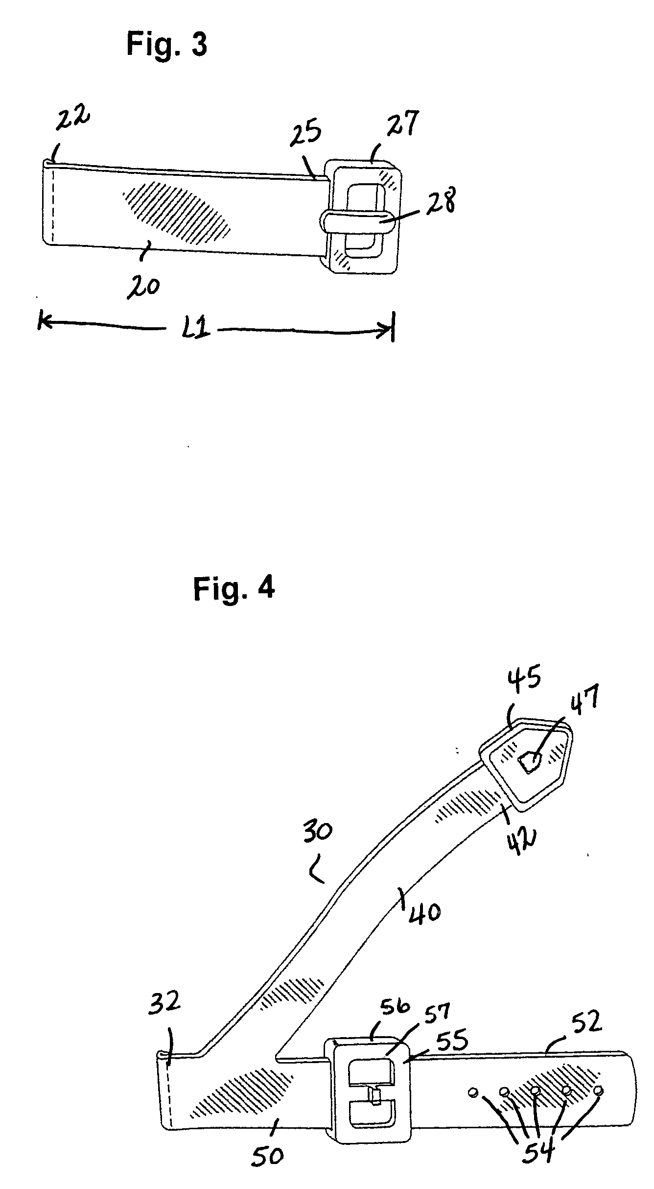
[0019]FIGS. 1-4 illustrate a device holding structure 10 made in accordance with the present invention. The drawings show the device holding structure 10 generally including a first band 20 (best shown in FIG. 3) and a second band 30 (best shown in FIG. 4) being used in association with a prior art watch casing 12. The casing 12 is the enclosure of the watch mechanism, with a watch face 11 on the upper side showing the time. The casing 12 can be shaped in various forms and is generally known in th...


PUM


Abstract

A device holding structure generally including a first band and a second band being used in association with a prior art device such as a watch casing. The first band includes a first end with means for attaching to connecting elements of the casing, and a buckle and a bar known in the art, and defines an angle such that when the device is placed upon the top of the wearer's hand the first band downwardly extends below the individual's fifth or smallest finger immediately above the wearer's wrist. The second band includes means for attaching to the connecting elements of the casing and first and second band members. The buckle is attached to one of a plurality of loops in the second band member such that the first band and second band member encircle the wearer's hand below the base of the wearer's thumb. The first band member passes between the wearer's thumb and index finger such that a clasp extends around the thumb and attaches to a connecting element of the second band member approximately below the wearer's thumb on the palm-side of the wearer's hand.

Description

CROSS REFERENCES TO RELATED APPLICATIONS[0001]U.S. Provisional Application for Patent No. 61 / 069,673, filed Mar. 17, 2008, with title “Method Of Wearing A Watch On The Back Of The Hand” which is hereby incorporated by reference. Applicant claim priority pursuant to 35 U.S.C. Par. 119(e)(i).[0002]Statement as to rights to inventions made under federally sponsored research and development: Not Applicable.BACKGROUND OF THE INVENTION[0003]1. Field of the Invention[0004]This invention relates generally to a structure for holding a device, such as a watch, and more particularly to a structure for holding a device on the back of the hand such that the face of the device is in view to the wearer at all times.[0005]2. Brief Description of Prior Art[0006]The wrist watch is known in the art and commonly includes a band that is known to be worn around the wearer's wrist. The common wrist watch, while generally considered as being convenient, has its imperfections. For example, it is very common...

Claims


Application Information

Patent Timeline
Patent Type & Authority Applications(United States)
IPC IPC(8): A44C5/14
CPCA44C5/0053Y10T24/4782Y10S24/16A44C5/14
Inventor DEVERS, BROCK L.
Owner DEVERS BROCK L
Why Eureka
Try Eureka