Cord for Rubber Reinforcement

a technology of rubber reinforcement and cord, which is applied in the direction of textile cables, yarn, textiles and paper, etc., can solve the problems of destroying the cord, cracking the adhesive layer between the primary twist thread and the adhesive layer, and the conventional cord for rubber reinforcement with the limited number of twists and limited twist directions not having sufficient bending fatigue resistance, etc., to achieve the effect of improving bending fatigue resistance and lowering dimensional stability

Inactive Publication Date: 2009-09-17
NIPPON SHEET GLASS CO LTD
View PDF6 Cites 7 Cited by
  • Summary
  • Abstract
  • Description
  • Claims
  • Application Information

AI Technical Summary

Benefits of technology

[0016]The present invention provides a cord for rubber reinforcement that excels in bending fatigue resistance, without lowering dimensional stability.

Problems solved by technology

A drawback of conventional cords for rubber reinforcement, however, is that, when the cord is bent, a shear force causes a crack in the adhesive layer (for example, RFL layer) that binds the primary twist threads in a cord and eventually destroys the cord from the point of cracking.
In other words, the conventional cords for rubber reinforcement with the limited number of twists and the limited twist direction do not have sufficient bending fatigue resistance.
When the cord is bent repeatedly, the crack first occurs in the adhesive layer between the primary twist threads.
The crack changes the overall balance of stress in the cord, creating strong stress that locally concentrates on each primary twist thread.
The concentration of stress breaks the strands making up the primary twist threads and eventually destroys the entire cord.
However, simply increasing the number of final twists produces a cord with poor dimensional stability that easily stretches, or leads to weak tensile strength.

Method used


Image

  • Cord for Rubber Reinforcement
  • Cord for Rubber Reinforcement

Examples


example 1

[0049]Three glass fibers (each being a bundle of 200 filaments having an average diameter of 9 μm, E-glass composition) were aligned with one another. After applying an aqueous treatment liquid shown in Table 1, the glass fibers were dried for one minute in a drying furnace that had been set to 150° C. As a result, a glass fiber strand (1) with a coating layer was obtained for Example 1. Note that the “solid content” in Table 1 means the amount of component other than the solvent or dispersion medium.

TABLE 1ComponentsContent (solid content)H-NBR (solid content 40 mass %)(*1)100 parts by massRF 10 parts by mass(*1)ZETPOL LATEX, manufactured by JAPAN ZEON CORPORATIONRF: resorcinol-formaldehyde condensation product (resorcinol-formalin condensation product)

[0050]The glass fiber strands (1) were primarily twisted at a rate of 0.4 times / 25 mm in Z direction to obtain a strand (A). Separately, the glass fiber strands (1) were primarily twisted at a rate of 3.0 times / 25 mm in S direction t...

example 2

Comparative Examples 1 to 5

[0052]Cords for rubber reinforcement (Example 2, Comparative Examples 1 to 5) were prepared as in Example 1 except for varying the number of primary twists, the number of final twists, and the direction of twist of the strands. The configurations of the respective cords are given in Table 3 below.

example 3

Comparative Example 6

[0053]Glass fiber strands (1) were prepared as in Example 1. The glass fiber strands (1) were primarily twisted at a rate of 1.0 time / 25 mm in Z direction to obtain a strand (A). Separately, the glass fiber strands (1) were primarily twisted at a rate of 2.0 times / 25 mm in S direction or Z direction to obtain a strand (B).

[0054]In this manner, three strands (A), four strands (B) with the primary twist in S direction, and four strands (B) with the primary twist in Z direction were prepared.

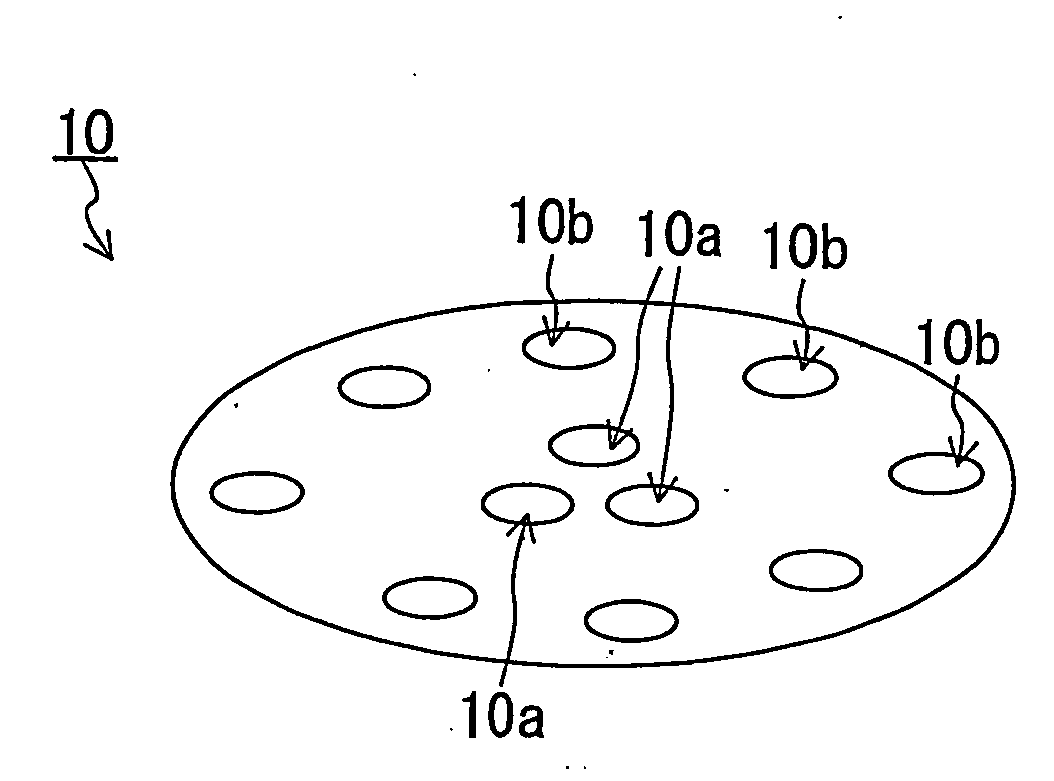
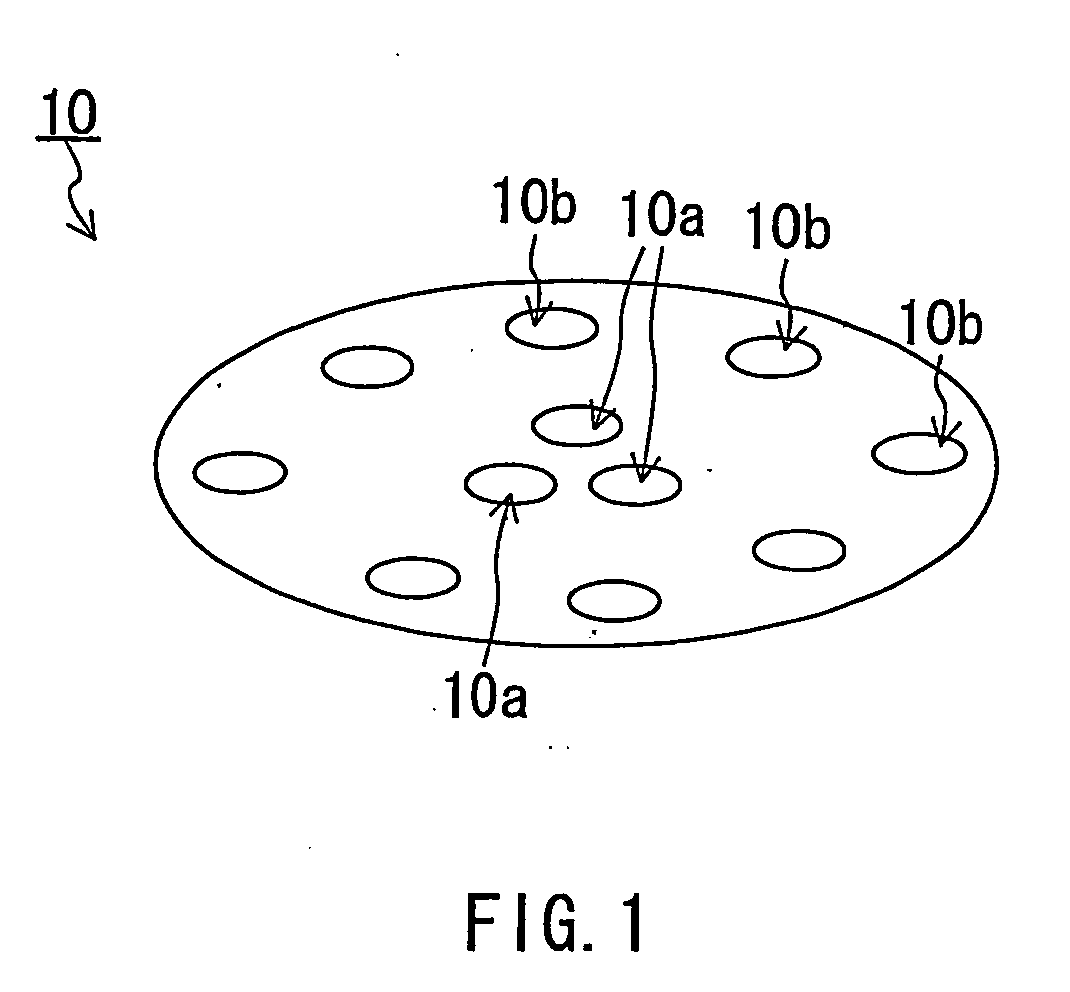
[0055]These eleven strands were laced through the apertures of a guide similar to the guide 10 shown in FIG. 1. The four strands (B) with the primary twist in Z direction, and the four strands (B) with the primary twist in S direction were alternately laced through eight apertures 10b. All strands were finally twisted at a rate of 2.0 times / 25 mm in S direction. In this manner, a cord for rubber reinforcement of Example 3 was obtained.

[0056]A reinforcing cord of Comparative Exa...


PUM

PropertyMeasurementUnit
diameteraaaaaaaaaa
widthaaaaaaaaaa
lengthaaaaaaaaaa

Abstract

A cord for rubber reinforcement of the present invention includes a core strand including a plurality of strands (A), and a plurality of strands (B) disposed around the core strand. In the core strand, the plurality of strands (A) are finally twisted, and each of the plurality of strands (A) is formed of a plurality of reinforcing fibers (A) that are primarily twisted. Each of the plurality of strands (B) is formed of a plurality of reinforcing fibers (B) that are primarily twisted, and the plurality of strands (B) are finally twisted to be disposed around the core strand. The direction of final twist of the plurality of strands (B) is the same as the direction of primary twist in at least one strand (B) selected from the plurality of strands (B). The number of primary twists in the strand (B) is greater than the number of primary twists in the strand (A), and/or the number of final twists of the strands (B) is greater than the number of final twists of the strands (A).

Description

TECHNICAL FIELD[0001]The present invention relates to a cord for rubber reinforcement.BACKGROUND ART[0002]Conventionally, cords for rubber reinforcement have been proposed.[0003]For example, JP2001-114906A discloses a cord for rubber reinforcement that excels in bending fatigue resistance by the construction in which primary twist strands are used as a core member (inner layer) and a side member (outer layer).[0004]JP2004-11076A discloses a cord for rubber reinforcement that excels in bending fatigue resistance and dimensional stability by the construction in which strands having different primary twist directions are used as a core member and a side member.[0005]JP10 (1998)-141445A, JP9 (1997)-42382A, JP1 (1989)-213478A, and JP59 (1984)-19744A disclose cords for rubber reinforcement in which the number of primary twists and final twists of strands is limited to improve bending fatigue resistance. Further, JP7 (1995)-144731A, JP10 (1998)-291618A, JP2005-8069A, and JP2005-22455A disc...

Claims


Application Information

Patent Timeline
Patent Type & Authority Applications(United States)
IPC IPC(8): D02G3/28
CPCD02G3/48D07B1/02D07B1/0613D07B2201/1044D07B2201/1052D07B2201/1056D07B2201/1068D07B2201/2061D07B2201/2057D07B2201/2025D07B2801/24D02G3/28
Inventor IMANISHI, HIDEKIAKIYAMA, MITSUHARUIIZUKA, HIROSHI
Owner NIPPON SHEET GLASS CO LTD
Why Eureka
Try Eureka