Adhesive tape dispenser

a tape dispenser and adhesive technology, applied in the field of adhesive tape dispensers, can solve the problems of inadequacies of medical institutions, incomplete exposure of tape rolls, and inability to meet the needs of medical institutions, and achieve the effect of convenient access and convenient access

Inactive Publication Date: 2009-09-17
CHUN NIEN PLASTIC LED
View PDF4 Cites 24 Cited by
  • Summary
  • Abstract
  • Description
  • Claims
  • Application Information

AI Technical Summary

Benefits of technology

[0003]The primary purpose of the present invention is to provide a novel tape dispenser herein to obviate the shortcomings of conventional tape dispensers in terms of sanitation and safety.
[0004]According to the present invention, the tape dispenser completely conceals its tape roll in a tightly closed housing. A removable cover extended from a major side or a top side of the tape dispenser's body is provided. At least a major side of the tape dispenser's body has a curved recession. As such, when the cover is opened, a section of the adhesive tape and a cutting edge at a front edge of a bottom side of the tape dispenser's body is exposed in a front opening and the recession for easy and convenient access.

Problems solved by technology

For this type of tape dispensers, the tape roll 20 is completely exposed and therefore could be easily contaminated.
In other words, these tape dispensers still are not appropriate for use in medical institutions where high degrees of sanitation and safety are required.

Method used


Image

  • Adhesive tape dispenser
  • Adhesive tape dispenser
  • Adhesive tape dispenser

Examples


first embodiment

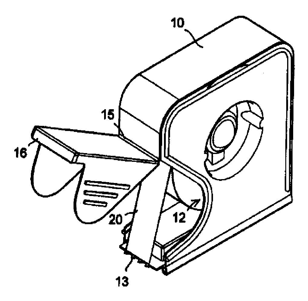
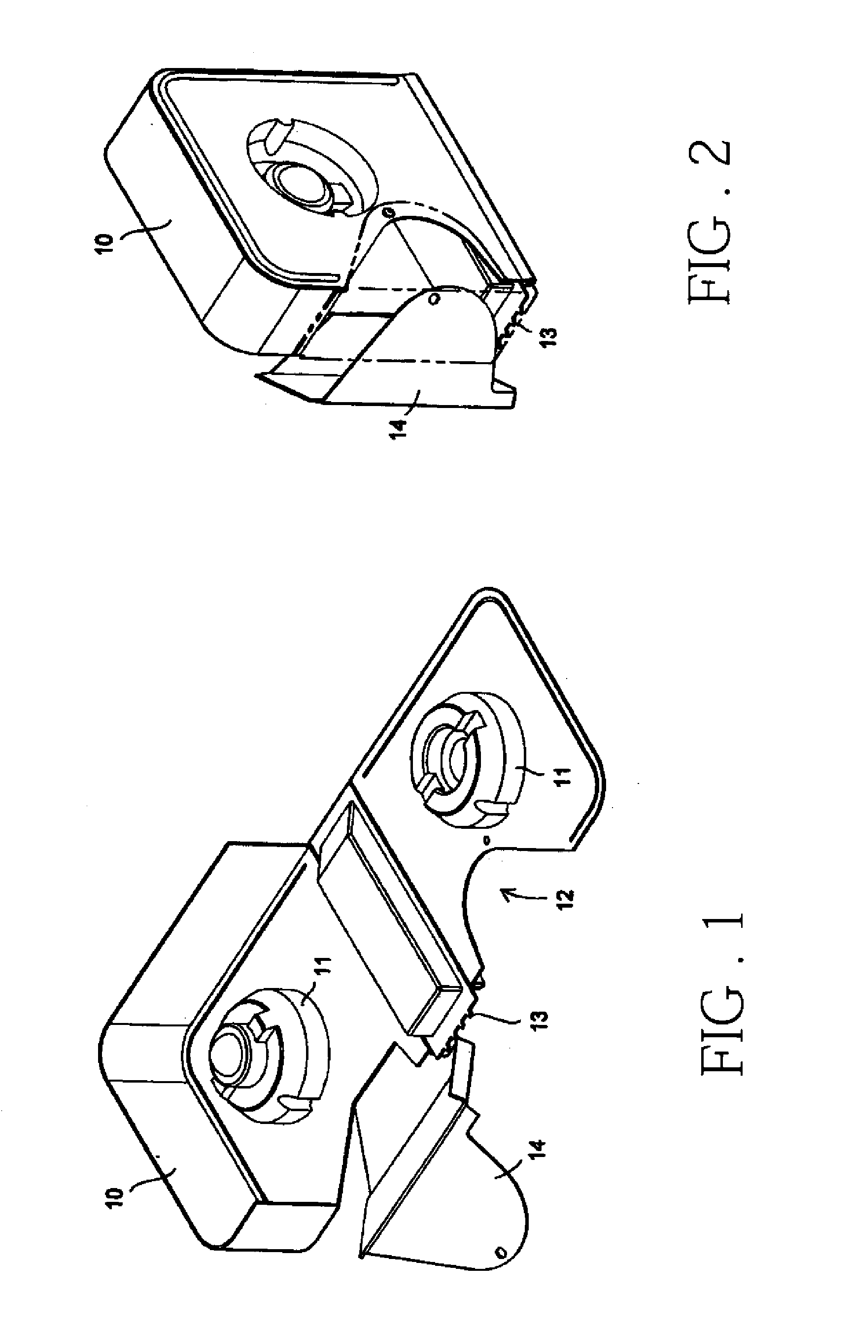
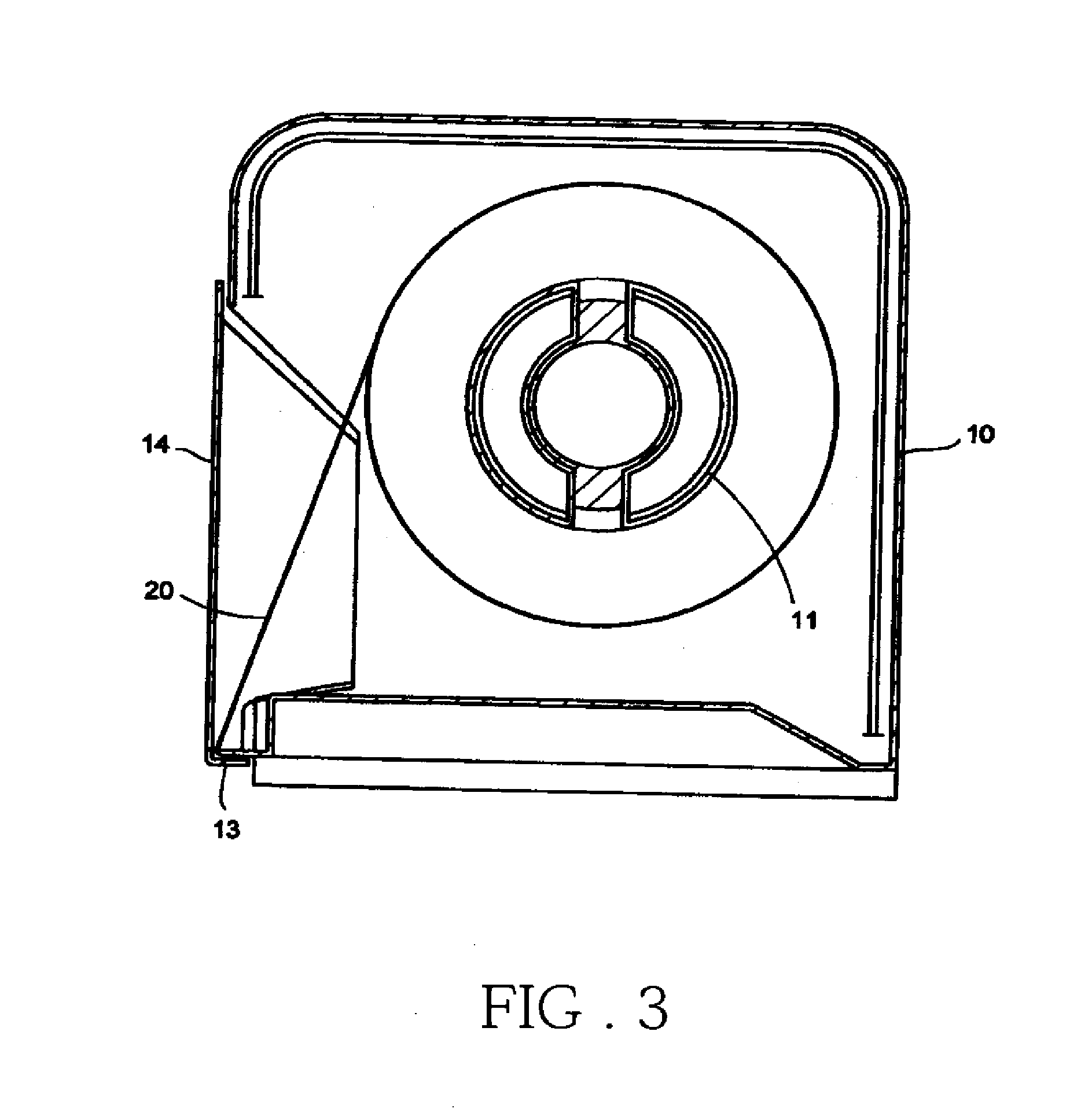
[0015]A tape dispenser according to the present invention is shown in FIGS. 1 to 3. The tape dispenser has an integrally formed body 10 that can be unfolded as shown in FIG. 1 and folded into a hollow casing with a front opening as shown in FIG. 2. The body 10 has two opposing major sides, each having a protrusion 11 on an inner surface of the major sides. When the body 10 is folded, the two protrusions 11 jointly form a hub for a tape roll 20 (see FIG. 3). The adhesive tape therefore could be pulled out of the body 10 from the tape roll 20 via the front opening and then cut by a saw-tooth cutting edge 13 positioned at a front edge of a bottom side of the body 10. Please note that the saw-teeth of the cutting edge 13 could be further sharpened by gradually decreasing its thickness towards their tips.

[0016]A first major side has a curved recession 12 along a front edge boarding on said front opening. On the other hand, a cover 14 is extended from a second major side opposite to the f...

second embodiment

[0017]FIGS. 4 and 5 show a tape dispenser according to the present invention. As illustrated, the cover 14 is hinged to or extended from a front side of the body 10 by a perforation 15. The two major sides of the body 10 have corresponding curved recessions 12 along their front edges bordering on the front opening, respectively. The cover 14 is appropriately shaped so that the front opening, the cutting edge 13, and the recessions 12 could be tightly closed and sealed inside the body 10 when the cover 14 is closed. Furthermore, the cutting edge 13 could be positioned slightly into the body 10 and a protection rim 16 extended from a front bottom edge of the cover 14 is arranged to cover the cutting edge 13 entirely and to provide additional safety guard against the sharp teeth of the cutting edge 13. The protection rim 16 could be designed so that it snaps onto the bottom side of the body 10 to achieve reliable locking of the cover 14 to the body 10.

[0018]According to the foregoing d...


PUM


Abstract

The tape dispenser completely conceals its tape roll in a tightly closed housing. A removable cover extended from a major side or a top side of the tape dispenser's body is provided. At least a major side of the tape dispenser's body has a curved recession. As such, when the cover is opened, a section of the adhesive tape and a cutting edge at a front edge of a bottom side of the tape dispenser's body is exposed in a front opening and the recession for easy and convenient access. As such, the tape dispenser provides higher degrees of sanitation and safety than the conventional tape dispensers.

Description

TECHNICAL FIELD OF THE INVENTION[0001]The present invention generally relates to adhesive tape dispensers, and more particularly to a tape dispenser having a high degree of sanitation and safety for medical institutions.DESCRIPTION OF THE PRIOR ART[0002]Adhesive tape dispensers, whether they are desktop dispensers or hand-held dispensers, are usually structured as shown in FIG. 6. As illustrated, the body 21 of the dispenser is formed by two parallel pieces joined together along their bottom edges by a lateral piece. The two pieces also forms a hub (not numbered) in the center for the installation of a tape roll 20. A cutting edge 22 is then provided at a front end of the lateral piece. For this type of tape dispensers, the tape roll 20 is completely exposed and therefore could be easily contaminated. As such, a tape dispenser as shown in FIG. 7 is usually used in hospitals or medical institutions where hygiene is a major concern. As illustrated, the tape roll 20 is almost completel...

Claims


Application Information

Patent Timeline
Patent Type & Authority Applications(United States)
IPC IPC(8): B65H35/07
CPCB65H35/0026B65H2402/443B65H35/0073Y10T225/241
Inventor CHANG, CHI-TSAI
Owner CHUN NIEN PLASTIC LED
Why Eureka
Try Eureka