
LCD connector for printed circuit boards

Inactive Publication Date: 2005-02-15
TYCO ELECTRONICS LOGISTICS AG (CH)
View PDF36 Cites 25 Cited by
  • Summary
  • Abstract
  • Description
  • Claims
  • Application Information

AI Technical Summary

Benefits of technology

It is therefore an advantage of the present invention to provide an improved LCD surface mount connector that obviates the above-described shortcomings of conventional elastomeric contacts.
to provide an improved LCD surface mount connector that obviates the above-described shortcomings of conventional elastomeric contacts.
It is another advantage of the present invention to provide an LCD surface mount connector that retains a plurality of contacts in an inexpensively molded insulative housing.
It is an additional advantage of the present invention to ensure that conductive elements of an LCD connector are correctly aligned with terminal pads of adjacent circuits during assembly of the connector between the circuits.
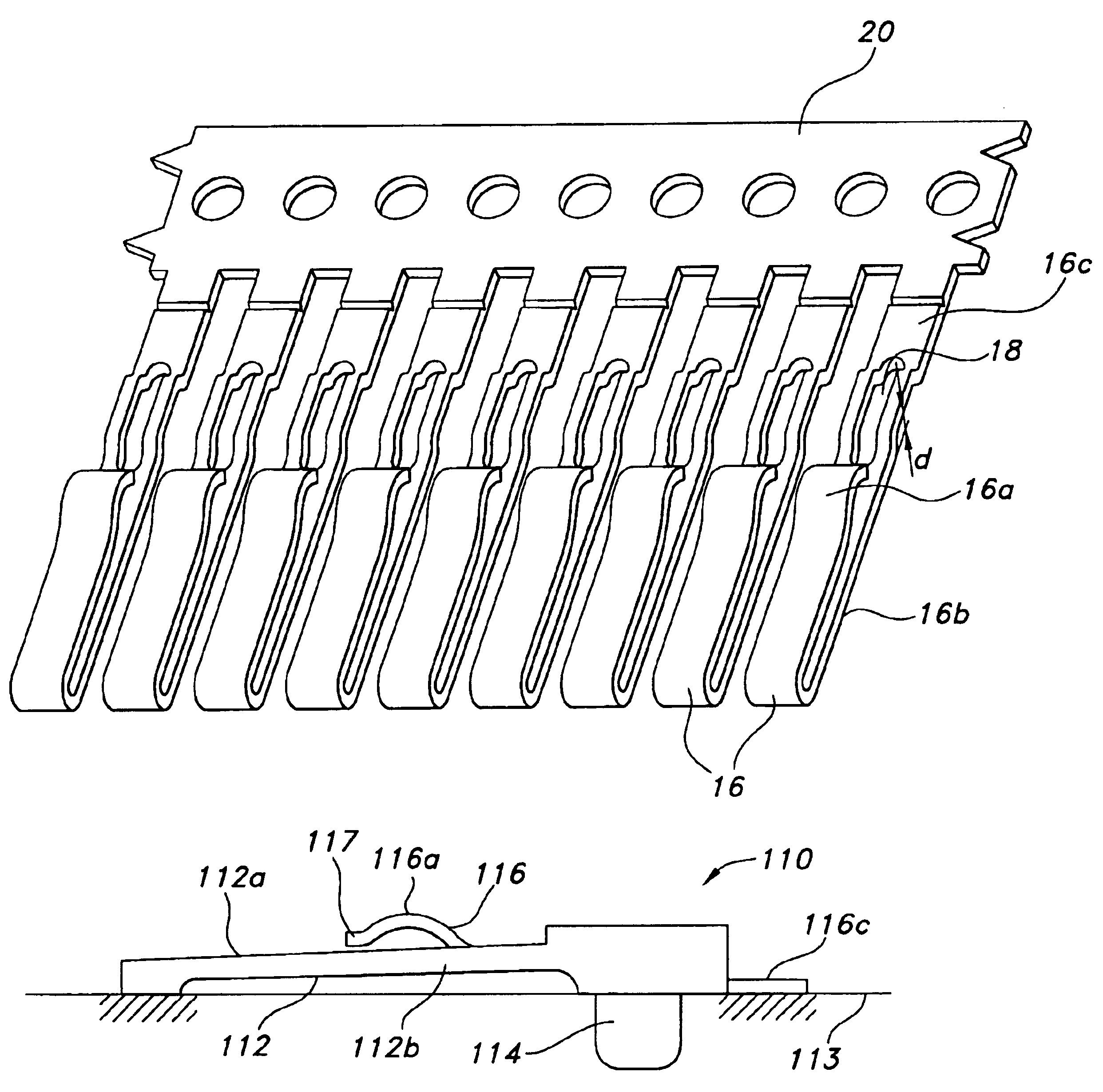
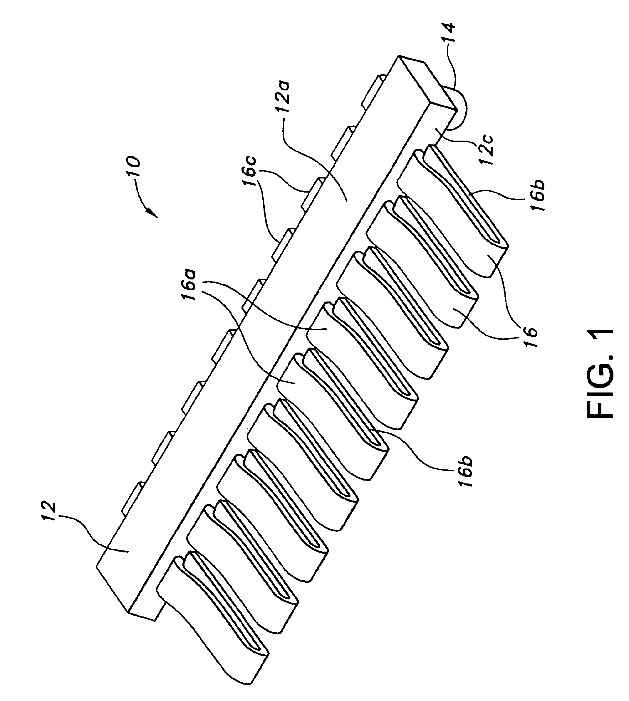
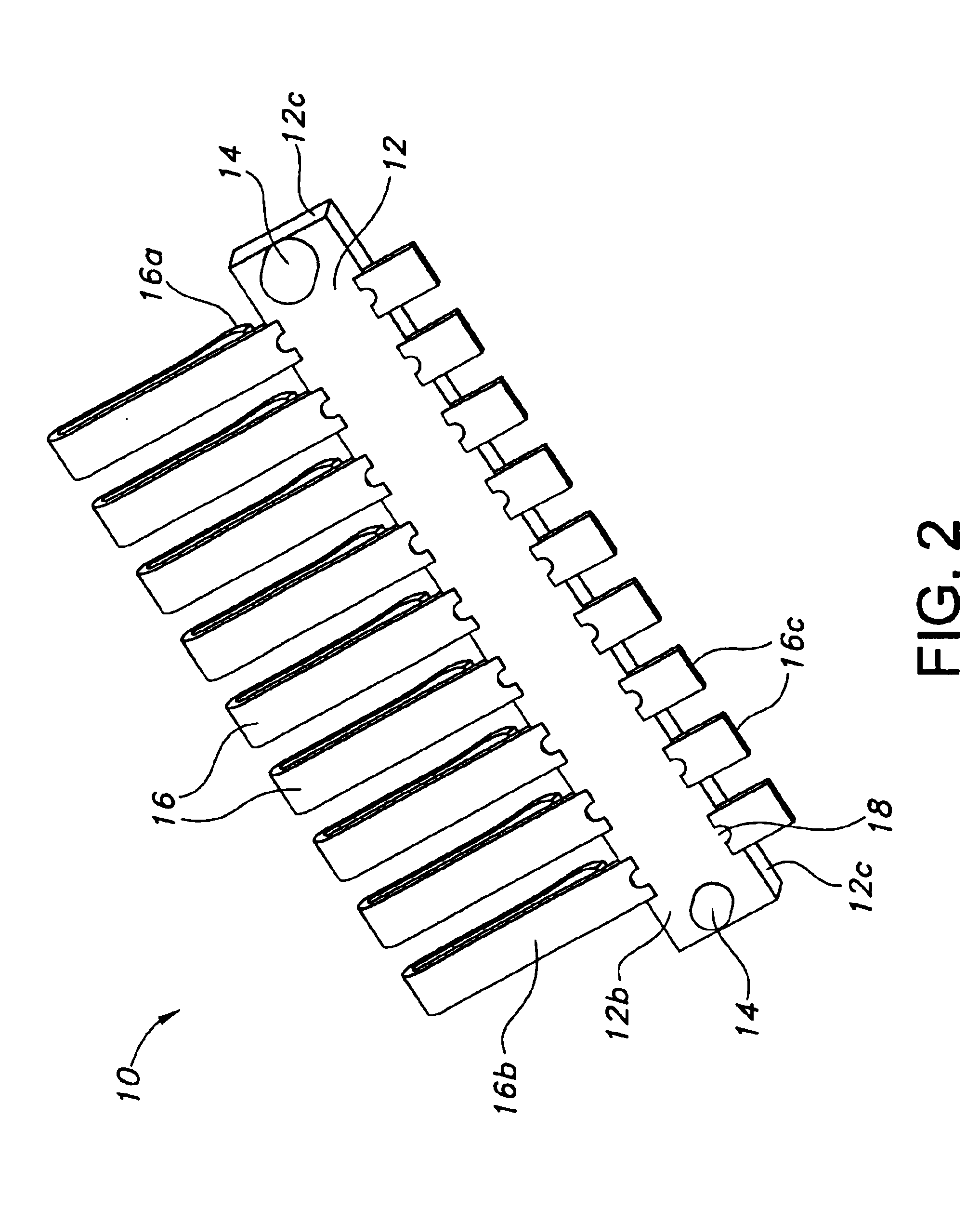
In accordance therefor with a particular arrangement of the invention, an electrical connector is provided for establishing electrical connection between a conductive portion of an LCD display and conductive elements of a printed circuit board. The connector includes a substantially planar integrally formed connector housing supportable on the printed circuit board, the housing having an upper surface, a lower surface and a peripheral wall. A plurality of electrical contacts are supported by the housing, each contact including an interior contact extent having a deflectable spring-like portion defined thereat. The interior contact extent provides for electrical engagement with the LCD conductor portion. Each electrical contact includes an exterior contact extent for termination to the printed circuit board. Each contact further includes a mid-section extent between the interior contact extent and the exterior contact extent, the midsection contact extents being secured to the housing allowing free connection of the interior contact extent to the printed circuit board and deflectable connection of the interior contact extent to the LCD conductor portions.

Problems solved by technology

Increasing use of LCDs in delicate and complex electronic devices, however, increases the number of applications in which numerous interconnections must be made between the LCD and the PWB.

Method used


Image

  • LCD connector for printed circuit boards
  • LCD connector for printed circuit boards
  • LCD connector for printed circuit boards

Examples


Embodiment Construction

The present invention provides for an LCD surface mount connector that eliminates the angular skew and consequential connection problems that are inherent in conventional elastomeric connectors. In one arrangement of the present invention shown with respect to FIGS. 1-11, the connector utilizes a plurality of contacts of varying configuration that are laterally spaced in an insulative connector housing. The contacts have resilient undulation spring-like portions at an extent thereof protruding normally from the housing and a tail portion for termination with a PWB. The contacts are fabricated for easy coupling with the housing wherein coupling effects alignment of the contacts and ensures proper mechanical and electrical engagement between the contacts and corresponding pads on the conductive portions of the LCD and the PWB.

Now referring to the drawing figures, FIGS. 1 and 2 show an LCD surface mount connector 10 in accordance with a particular arrangement of the present invention. ...


PUM


Abstract

An electrical connector for establishing electrical connection between a conductive portion of an LCD display and conductive elements of a printed circuit board comprises a substantially planar insulative connector housing and a plurality of electrical contacts supported thereby. Each contact includes a deflectable spring-like portion for resilient engagement with the LCD display and a tail portion for conductive engagement with the printed circuit board. Each contact further includes therebetween a mid-section secured to the insulative housing. The contacts are supported in the housing in laterally spaced disposition with respect to each other, and are adapted to provide sufficient normal forces to maintain sufficient mechanical and electrical connection between the connector and each of an LCD display and a printed circuit board. Contact free ends may be captured in a slot in the housing and the housing may include a flexible extent to provide increased contact pressure upon mating.

Description

FIELD OF THE INVENTIONThis invention is directed to the manufacture of a connector for liquid crystal displays (“LCDs”) that is adapted for electrical connection of an LCD panel and a conductive portion of a printed wiring board (PWB) or printed circuit board (PCB). This invention is further directed to a method of affixing an LCD panel to a PWB or PCB through an insulative connector having a plurality of contacts mounted thereon. As used herein, the terms PWB and PCB will be used interchangeably to denote a substrate having conductive elements to which an LCD is electrically connected.BACKGROUND OF THE INVENTIONLiquid crystal displays (“LCDs”) are being aggressively integrated into a multitude of contemporary electronic devices that previously employed cathode ray tubes (CRTs). “Liquid crystal” is a term that indicates the status of a substance that is neither solid nor liquid. When coming into contact with a grooved surface in a fixed direction, liquid crystal molecules line up in...

Claims


Application Information

Patent Timeline
IPC IPC(8): H01R12/16H01R12/00H01R13/26H01R13/02G02F1/1345G09F9/00H01R13/15H01R13/405H01R13/46H01R24/00H01R107/00
CPCH01R12/7076H01R13/26
Inventor CHIANG, MICHAEL CHUNG-TAKNOERNSCHILD, STEVEN WALKERSTARNES, STANLEY EARLELKHATIB, HESHAM K.WEBER, DALE ALAN
Owner TYCO ELECTRONICS LOGISTICS AG (CH)
Learn More