Geared cam expandable interbody implant and method of implanting same

a technology of interbody implants and cams, applied in the field of spinal implants, can solve problems such as lack of reliable ability for fine adjustmen

Active Publication Date: 2018-11-27
WARSAW ORTHOPEDIC INC
View PDF62 Cites 24 Cited by
  • Summary
  • Abstract
  • Description
  • Claims
  • Application Information

AI Technical Summary

Benefits of technology

[0003]It is an object of the present invention to provide an expandable spinal implant which obviates one or more of the shortcomings of the related art.
[0004]It is another object of the present invention to provide an expandable spinal implant for insertion into a patient's disc space between an upper vertebral body and a lower vertebral body. The implant has a proximal end and a distal end defining a mid-longitudinal axis therebetween, and is expandable between a collapsed position, a partially-expanded position, and a fully-expanded position.
[0011]It is a further object of the present invention to provide a method of implanting the expandable spinal implant described above into a patient's disc space between an upper vertebral body and a lower vertebral body. The method includes inserting the implant into a surgically-prepared disc space, in the collapsed position, using an implant insertion tool, rotating the rotating portion, defining a rotational motion, translating the rotational motion of the rotating portion into a linear motion of the yoke toward the distal end of the implant, rotating the spur gears with respect to the yoke, thereby walking the spur gears along the projecting teeth of the respective upper and lower racks, and expanding the implant through the partially-expanded position to the fully-expanded position. The insertion tool includes an outer hollow shaft, an inner hollow shaft configured to pass through the outer shaft, and an elongated driver configured to pass through the inner hollow shaft. The elongated driver has a blunt distal end configured to contact a portion of the implant. Application of a movement to the elongated driver is transferred to the implant, forcing the implant into the disc space. After removal of the elongated driver, bone growth material can be routed through the inner shaft and into the implant.

Problems solved by technology

The existing expandable implants have been known at least to (1) apply an undesireable excessive initial expansion force to the disc space, (2) apply an irregular expansion force to the disc space, and (3) lack a reliable capability for fine adjustment.

Method used


Image

  • Geared cam expandable interbody implant and method of implanting same
  • Geared cam expandable interbody implant and method of implanting same
  • Geared cam expandable interbody implant and method of implanting same

Examples


Embodiment Construction

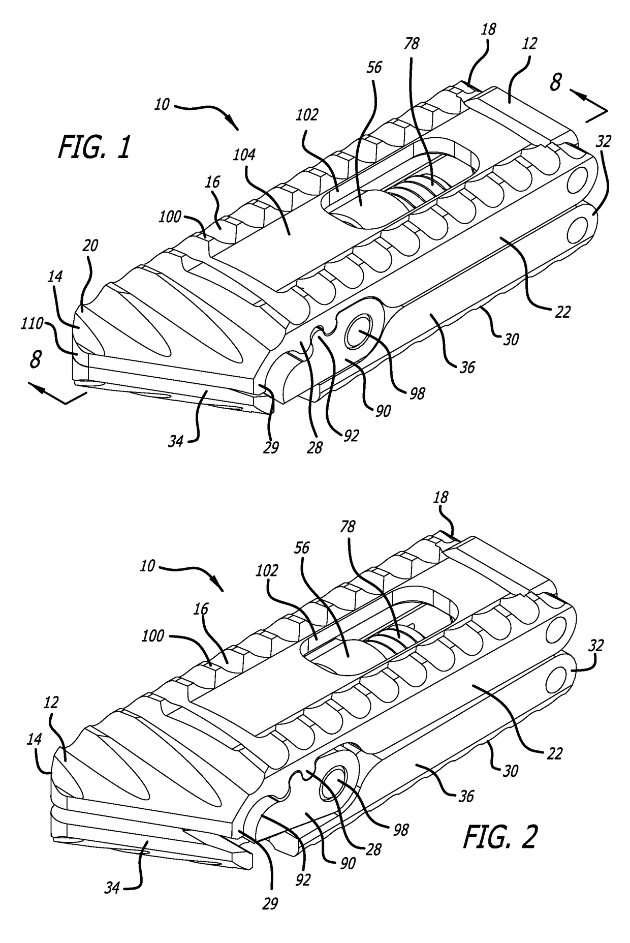
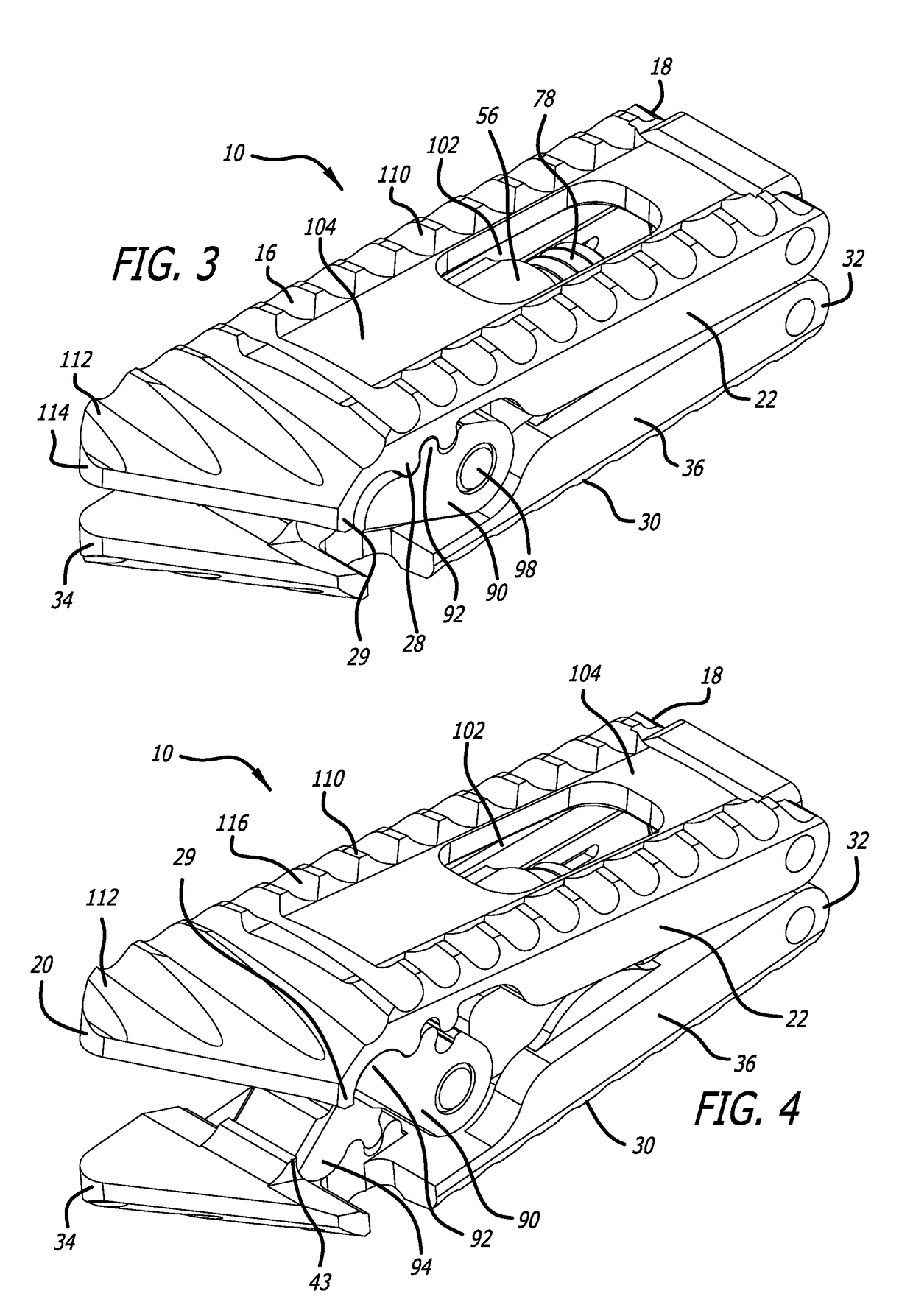
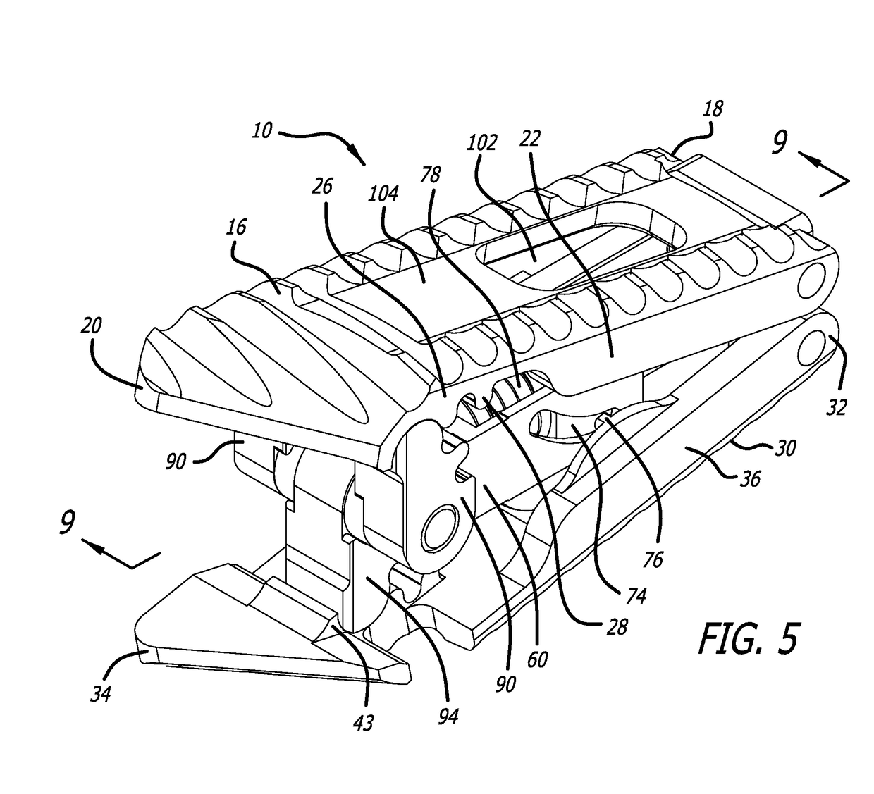
[0053]A geared cam expandable spinal implant 10 is configured to be inserted in a surgically-enhanced disc space between an upper vertebral body and an adjacent lower vertebral body. The implant 10 includes a proximal end 12 and a distal end 14, defining a mid-longitudinal axis L-L therebetween.

[0054]In one embodiment, the implant 10 includes an upper endplate 16. As depicted in FIGS. 6, 8, and 9, the upper endplate 16 includes a proximal end 18, a distal end 20, side surfaces 22, and an inner surface 24. The inner surface 24 includes an upper rack portion 26, which includes downwardly-projecting teeth 28, and a distal-most downwardly-projecting tooth 29.

[0055]In one embodiment, the implant 10 includes a lower endplate 30. The lower endplate 30 includes a proximal end 32, a distal end 34, side surfaces 36, and an inner surface 38. The inner surface 38 includes a lower rack portion 40, which includes upwardly-projecting teeth 42, and a distal-most upwardly-projecting tooth 43.

[0056]I...


PUM


Abstract

A geared cam expandable spinal implant. Rotational motion of a rotating portion is translated into linear motion of a yoke, which moves geared cams at the distal end of the implant to mate with, and walk along, teeth of corresponding racks. The walking of the gear cam teeth along the rack teeth creates a regular rate of implant expansion, reduces initial excessive expansion force applied to the implant, and provides fine adjustment of the expansion rate and force.

Description

FIELD OF THE INVENTION[0001]The present invention relates to a spinal implant, and a method for implanting the implant in a patient's disc space between two adjacent vertebral bodies. More particularly, the present invention relates to an expandable spinal implant including geared cams, configured to expand within the patient's disc space, from a collapsed position to an expanded position.DESCRIPTION OF THE RELATED ART[0002]Expandable spinal implants are known. Existing expandable spinal implants use conventional “4-bar” and “crank slider” expansion mechanisms. Following insertion, while in the collapsed position, into a surgically-enhanced disc space, the existing expandable spinal implants are expanded. The existing expandable implants have been known at least to (1) apply an undesireable excessive initial expansion force to the disc space, (2) apply an irregular expansion force to the disc space, and (3) lack a reliable capability for fine adjustment. Existing expandable implants...

Claims


Application Information

Patent Timeline
Patent Type & Authority Patents(United States)
IPC IPC(8): A61F2/44A61F2/46A61F2/30
CPCA61F2/447A61F2/4611A61F2002/30556A61F2002/4475A61F2002/4627A61F2002/30507A61F2002/3054A61F2002/30158A61F2002/30411A61F2002/30471A61F2002/4629A61F2002/30523A61F2002/30538A61F2002/4625A61F2/442A61F2/4603A61F2002/30579A61F2/4455A61F2002/30593A61F2002/30485A61F2002/30522
Inventor DEWEY, JONATHAN M.ARMSTRONG, WILLIAM D.
Owner WARSAW ORTHOPEDIC INC
Why Eureka
Try Eureka