Airplane engine pylon comprising at least one protruding element to generate a vortex of the airflow

a technology of airflow and engine, which is applied in the direction of airflow influencers, aircraft power plant components, transportation and packaging, etc., can solve the problems of discontinuity in the leading edge, degrading the aerodynamic performance of the aircraft, and in particular the maximum value of the lift coefficient of the wing, so as to reduce the aerodynamic disturbance

Active Publication Date: 2009-09-17
AIRBUS OPERATIONS (SAS)
View PDF13 Cites 25 Cited by
  • Summary
  • Abstract
  • Description
  • Claims
  • Application Information

AI Technical Summary

Benefits of technology

[0024]The pylon has a forward edge extending substantially forward of the leading edge of the wing between a forward upper portion connected to the wing in the forward intermediate region and a forward lower portion connected to a nacelle of the engine. To reduce aerodynamic disturbances associated with the interruption of the high-lift device, the pylon has, on the forward edge, a protruding element of narrow elongate shape that is oriented substantially in a longitudinal direction of the forward edge, such that during flight at a high angle of attack of the aircraft, the protruding element generates at least one vortex of the aerodynamic flow that is propagated toward the forward intermediate region above the wing.

Problems solved by technology

For reasons of engine ground clearance when the aircraft is on the ground, it is not possible, however, for the engines to be placed much below the wing structure.
This interruption in the high-lift device introduces a discontinuity in the leading edge when said device is in the deployed position, this being the source of aerodynamic flow disturbances.
The interruption in the high-lift device in the region of the pylon is a cause of premature airflow separations on the suction side of the wing, these separations degrading the aerodynamic performance of the aircraft and, in particular, the maximum value of the lift coefficient of the wing.
This solution has the disadvantage of requiring a pylon of complex geometry whose shape is not compatible with a maximum reduction of drag in cruise mode.
This solution has the disadvantage of introducing a drag penalty when the aircraft is in cruise mode.
Furthermore, given their dimensions, it may prove a difficult operation to install the vanes on account of the movable elements of the nacelle and the need for precise aerodynamic positioning.
Moreover, the vanes may introduce constraints in the conditions of interchangeability of an engine, with its nacelle, when the engine can be fitted on various models of aircraft including some without vanes or with different vanes.

Method used


Image

  • Airplane engine pylon comprising at least one protruding element to generate a vortex of the airflow
  • Airplane engine pylon comprising at least one protruding element to generate a vortex of the airflow
  • Airplane engine pylon comprising at least one protruding element to generate a vortex of the airflow

Examples


Embodiment Construction

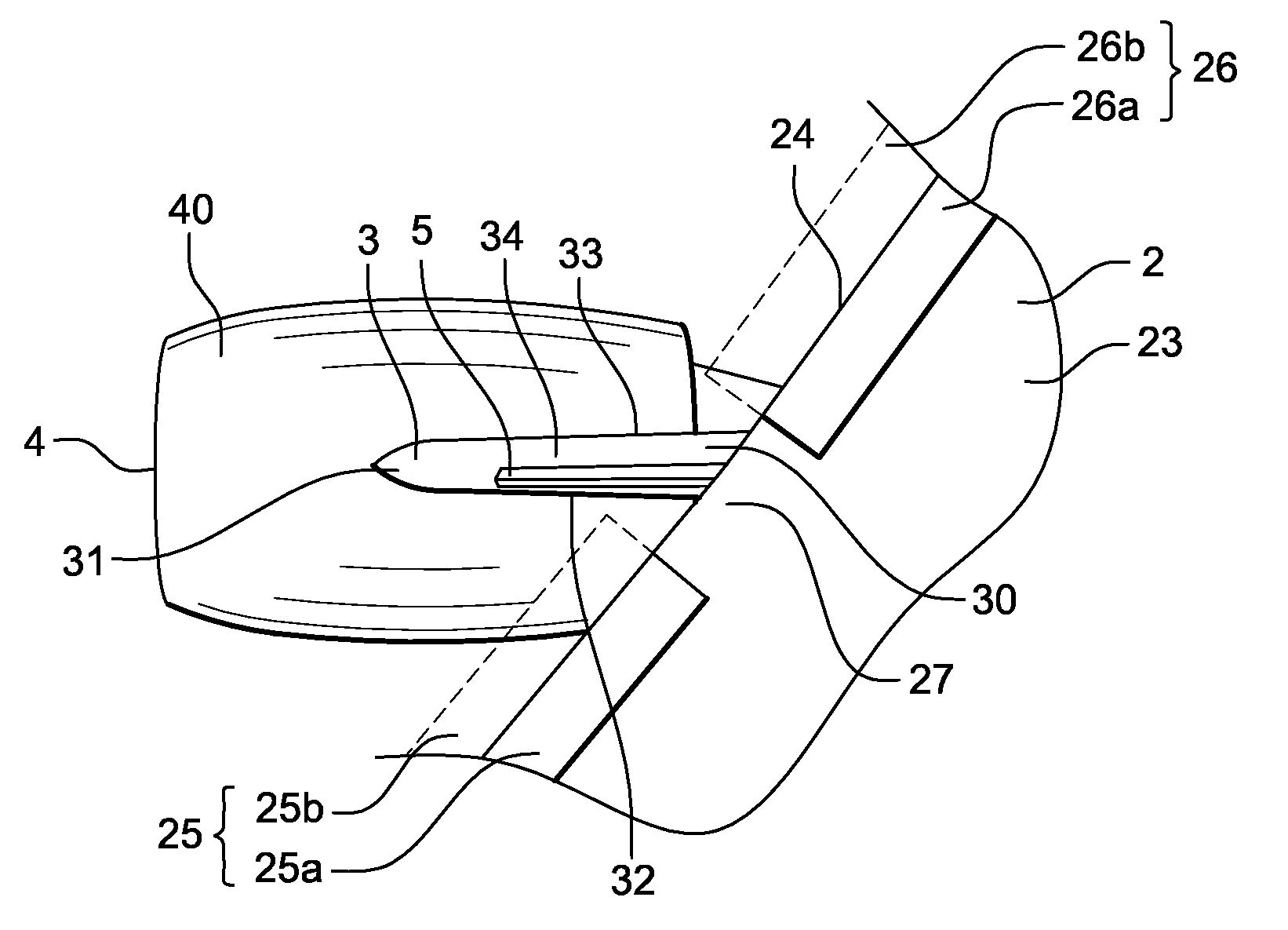
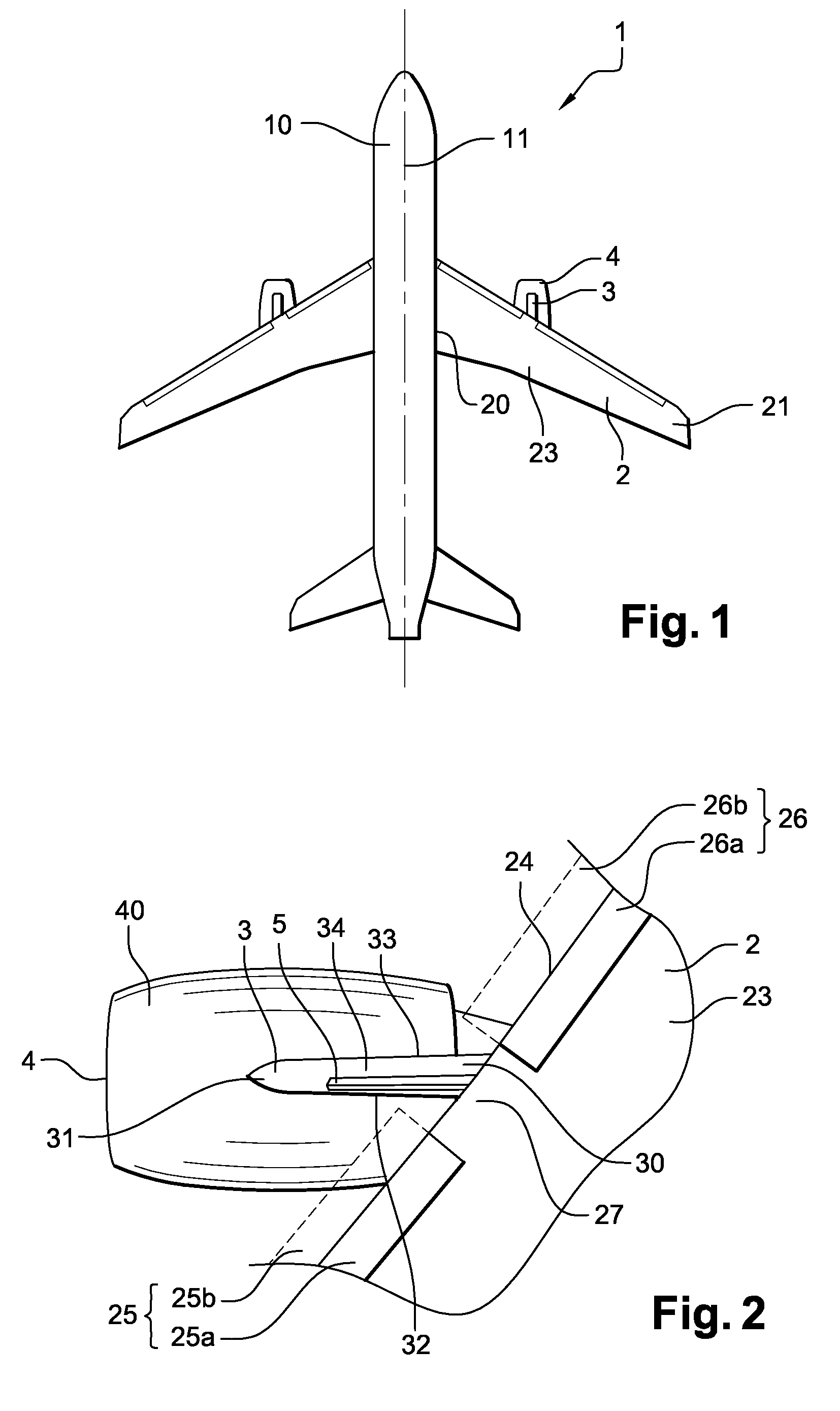
[0036]The disclosed embodiments find an application in aircraft having wing arrangements of the type comprising engines suspended below the wings by suspension pylons. FIG. 1 shows an aircraft 1 of this type as seen from above.

[0037]The aircraft 1 has a fuselage 10 defining a longitudinal axis 11 which is oriented substantially in a direction of travel of said aircraft.

[0038]In the remainder of the description, any reference to forward direction is to be considered along the longitudinal axis 11 as corresponding to the direction of normal travel of the aircraft 1 in flight. Any reference to aft direction corresponds to the opposite direction along the longitudinal axis 11.

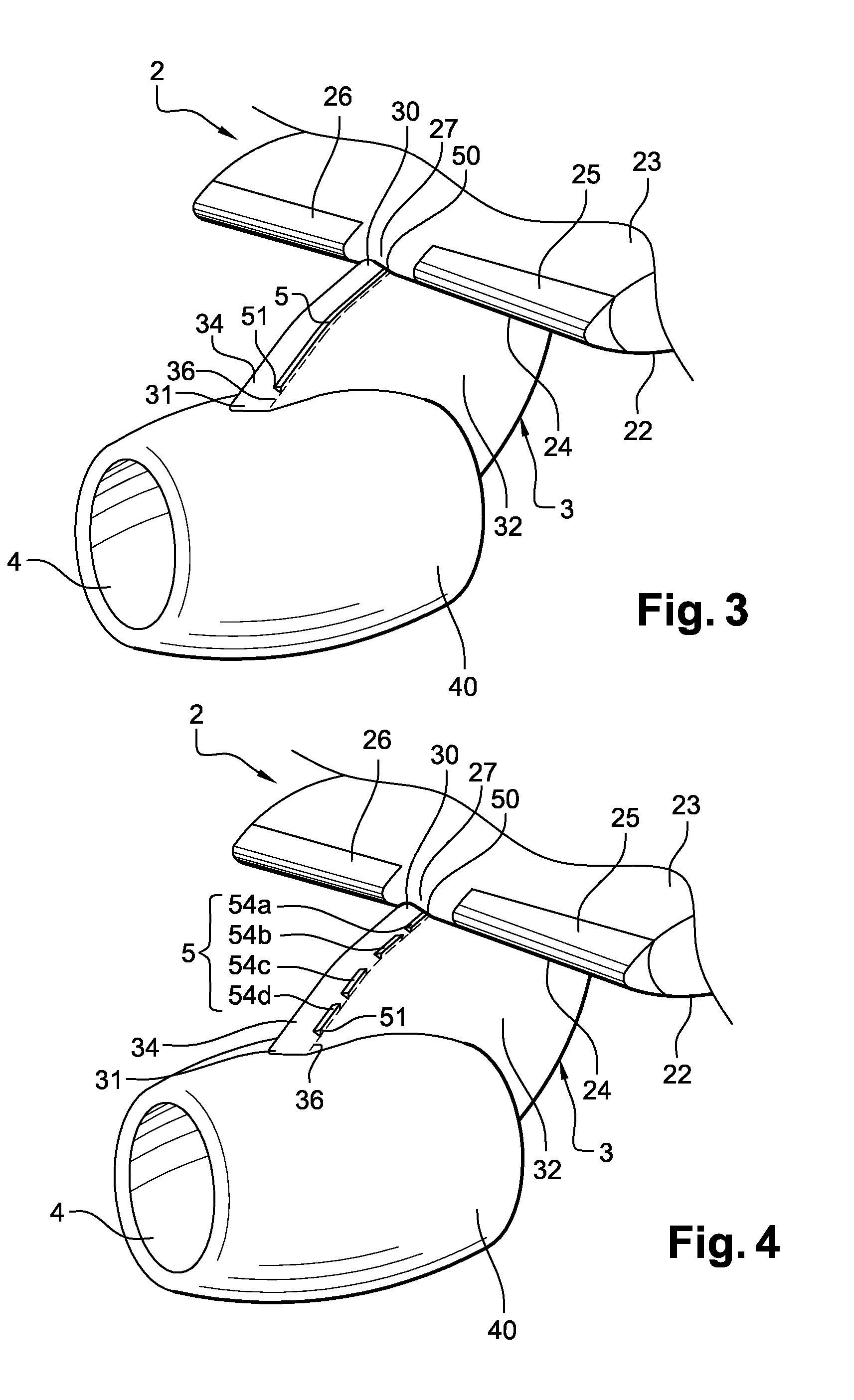
[0039]The aircraft 1 is provided, laterally with respect to the fuselage 10, with a wing arrangement comprising a wing 2 below which at least one engine 4 is fastened by way of a suspension pylon 3.

[0040]The wing 2 has a root 20 on the fuselage 10 side and a free end 21 on the opposite side to said root. The wing 2...


PUM


Abstract

A wing arrangement of an aircraft has a wing and at least one pylon for suspending an engine below the wing. The wing has a leading edge with a high-lift device, which is able to move between a deployed position in which the high-lift device projects forward of the leading edge, and which is interrupted in a forward intermediate region of the wing located at the leading edge, the pylon having a forward edge extending forward of the leading edge of the wing between a forward upper portion connected to the wing in the forward intermediate region and a forward lower portion connected to a nacelle of the engine. An element of narrow elongate shape protrudes longitudinally from the forward edge and, during flight at a high angle of attack of the aircraft, generates a vortex of aerodynamic flow that is propagated toward the forward intermediate region above the wing.

Description

CROSS-REFERENCE TO RELATED APPLICATIONS[0001]This application claims priority to French Application No. 08 51670, filed on 14 Mar. 2008, the disclosure of which is incorporated herein by reference in its entirety.BACKGROUND[0002]1. Field[0003]The disclosed embodiments relate to an aircraft wing arrangement of the type comprising a wing and also at least one pylon for suspending an engine below this same wing.[0004]More specifically, the disclosed embodiments relate to a wing arrangement for an aircraft whose wings have high-lift devices which are interrupted at the interface between the wing and a pylon, resulting in a reduction of the lift capabilities of the wing during flight at a high angle of attack.[0005]2. Brief Description of Related Developments[0006]In modern aircraft, more specifically civilian transport aircraft, it is known practice to suspend the engines below the wing structure using suspension pylons.[0007]Such pylons are working structures which transmit the forces ...

Claims


Application Information

Patent Timeline
Patent Type & Authority Applications(United States)
IPC IPC(8): B64C3/00
CPCB64C7/02B64C23/06Y02T50/162B64D29/02B64D27/18Y02T50/10
Inventor BONNAUD, CYRILDANTIN, STEPHANIEDEFOS, MARJORIEFOL, THIERRY
Owner AIRBUS OPERATIONS (SAS)
Why Eureka
Try Eureka