

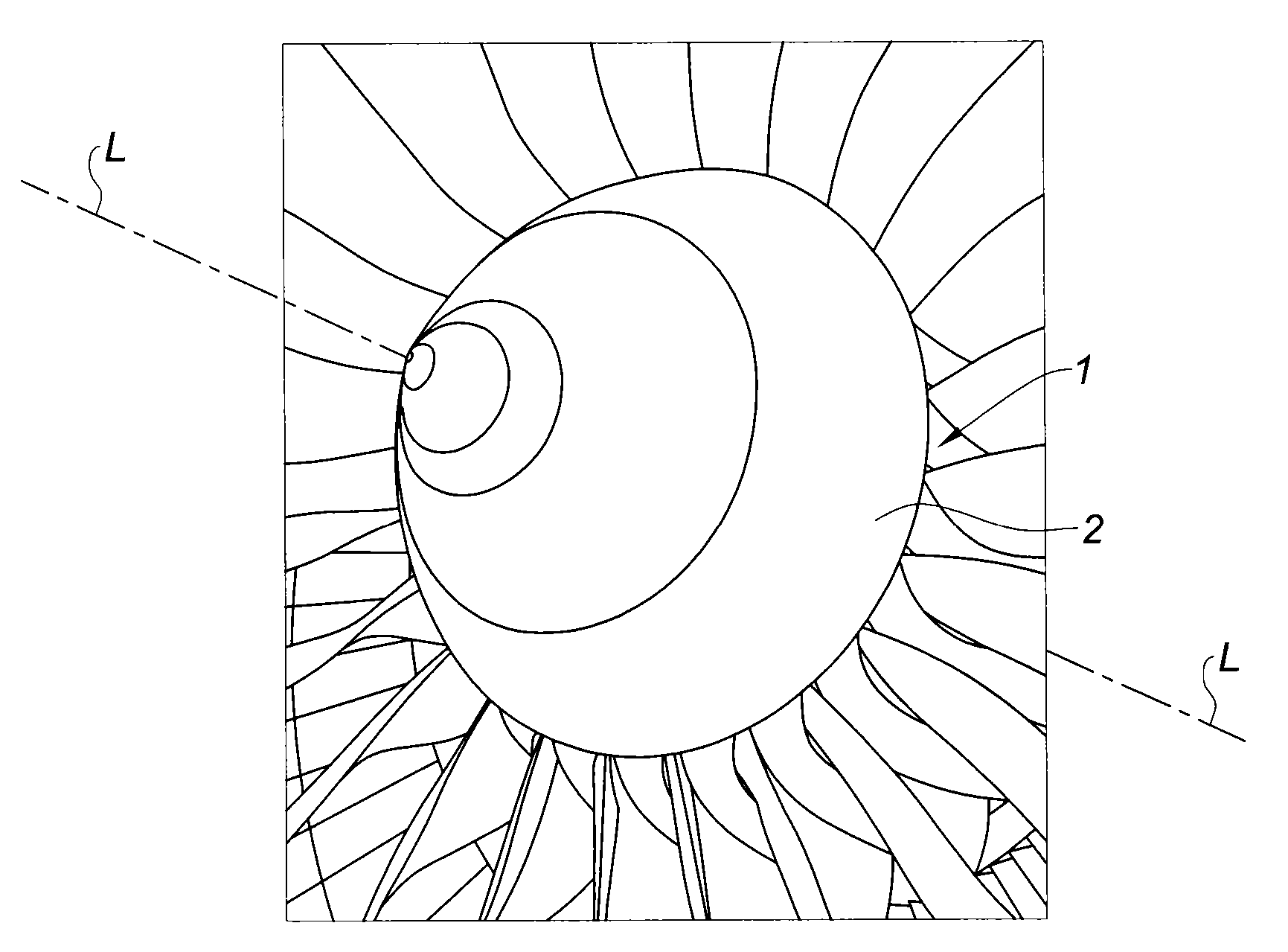
System for attaching a turbojet engine spinner
a turbojet engine and spinner technology, applied in the field of turbojet engines, can solve the problems of increasing the drag of the turbine engine, fuel consumption, and encouraging aerodynamic losses, and achieve the effect of reducing aerodynamic disturbances
- Summary
- Abstract
- Description
- Claims
- Application Information
AI Technical Summary
Benefits of technology
Problems solved by technology
Method used
Image

Examples
first embodiment
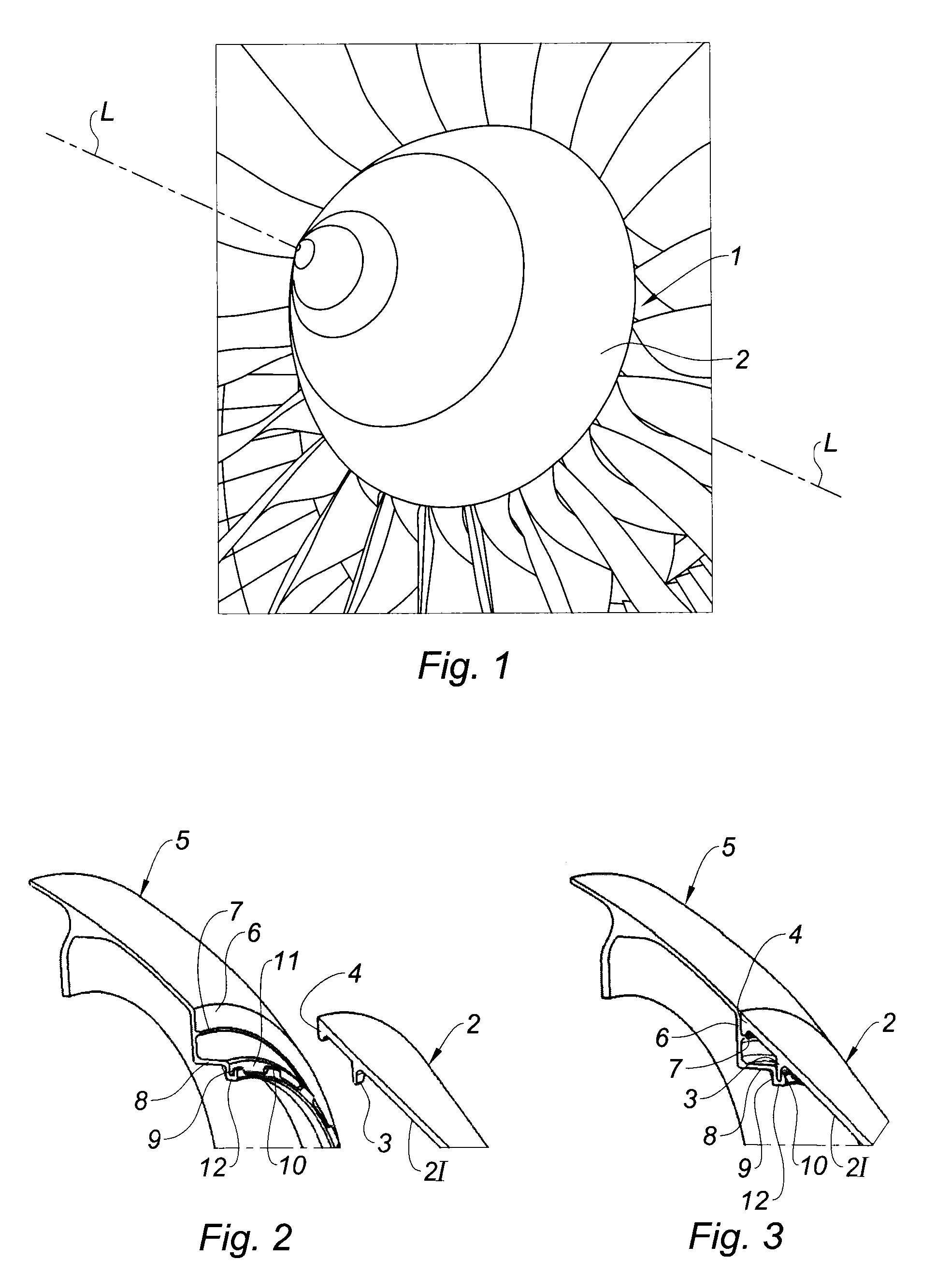
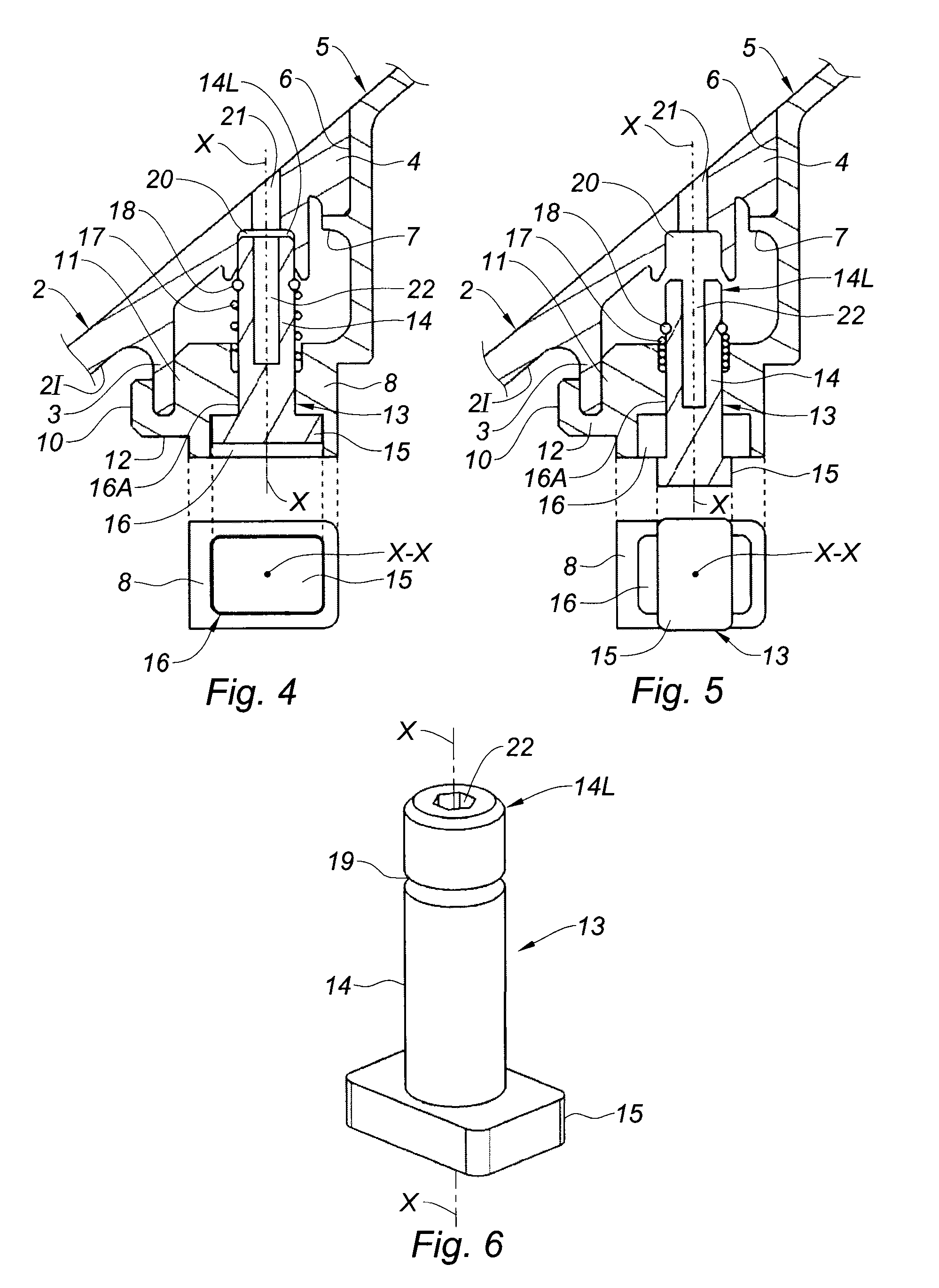
[0045]Moreover, in a first embodiment according to the present invention, and illustrated in FIGS. 4 to 6, the rotation-proofing means comprise two rotation-proofing pegs 13 which are diametrically opposed so as to maintain the dynamic balance of the fan rotor 1, and which are able, independently of one another, to occupy at least one of the following two positions:[0046]a locked position (FIG. 4) in which the spinner 2 is prevented from rotating with respect to the fan rotor 1; and[0047]an unlocked position (FIG. 5) in which the spinner 2 is allowed to rotate with respect to the fan rotor 1.
[0048]As FIGS. 4 to 6 show, each rotation-proofing peg 13 comprises a cylindrical shank 14, of axis X-X, and a head 15 secured to one longitudinal end of the shank 14.
[0049]In this first example, the head 15 of the peg 13 is of flat rectangular shape. When a rotation-proofing peg 13 is in the locked position (FIG. 4), its head 15 is able to enter a corresponding main housing 16 formed in the wal...
second embodiment
[0073]In a second embodiment according to the invention and depicted in FIGS. 7 to 9, the rotation-proofing means comprise two rotation-proofing pegs 23 which are diametrically opposed and able, independently of one another, to occupy at least a locked position (FIG. 7) and an unlocked position (FIG. 8). Each rotation-proofing peg 23 is formed of a cylindrical shank 24 of axis X-X, and of a head 25 secured to one longitudinal end of the shank 24.
[0074]In this second example, the head 25 of the pegs 23 is in the form of a trapezoidal prism. When a rotation-proofing peg 23 is in the locked position (FIG. 7), its head 25 is inserted in a main housing 26 formed for that purpose in the flange 5 and the spinner 2 once these two have been joined together. In other words, the main housing 26 is defined when the spinner 2 is mounted on the flange 5 and correctly angularly oriented in relation thereto. That portion of the main housing 26 that is made in the flange 5 corresponds to a recess ma...
PUM
 Abstract
Description
Claims
Application Information