Door latch device in a motor vehicle

a technology for latching devices and motor vehicles, applied in anti-theft devices, lock applications, doors, etc., can solve the problem of high manufacturing cost of providing two motors

Active Publication Date: 2009-10-01
MITSUI KINZOKU ACT
View PDF12 Cites 36 Cited by
  • Summary
  • Abstract
  • Description
  • Claims
  • Application Information

AI Technical Summary

Problems solved by technology

To carry out both double locking and childproof locking, it is necessary to provide two motors involving high cost for manufacturing.

Method used


Image

  • Door latch device in a motor vehicle
  • Door latch device in a motor vehicle
  • Door latch device in a motor vehicle

Examples


Embodiment Construction

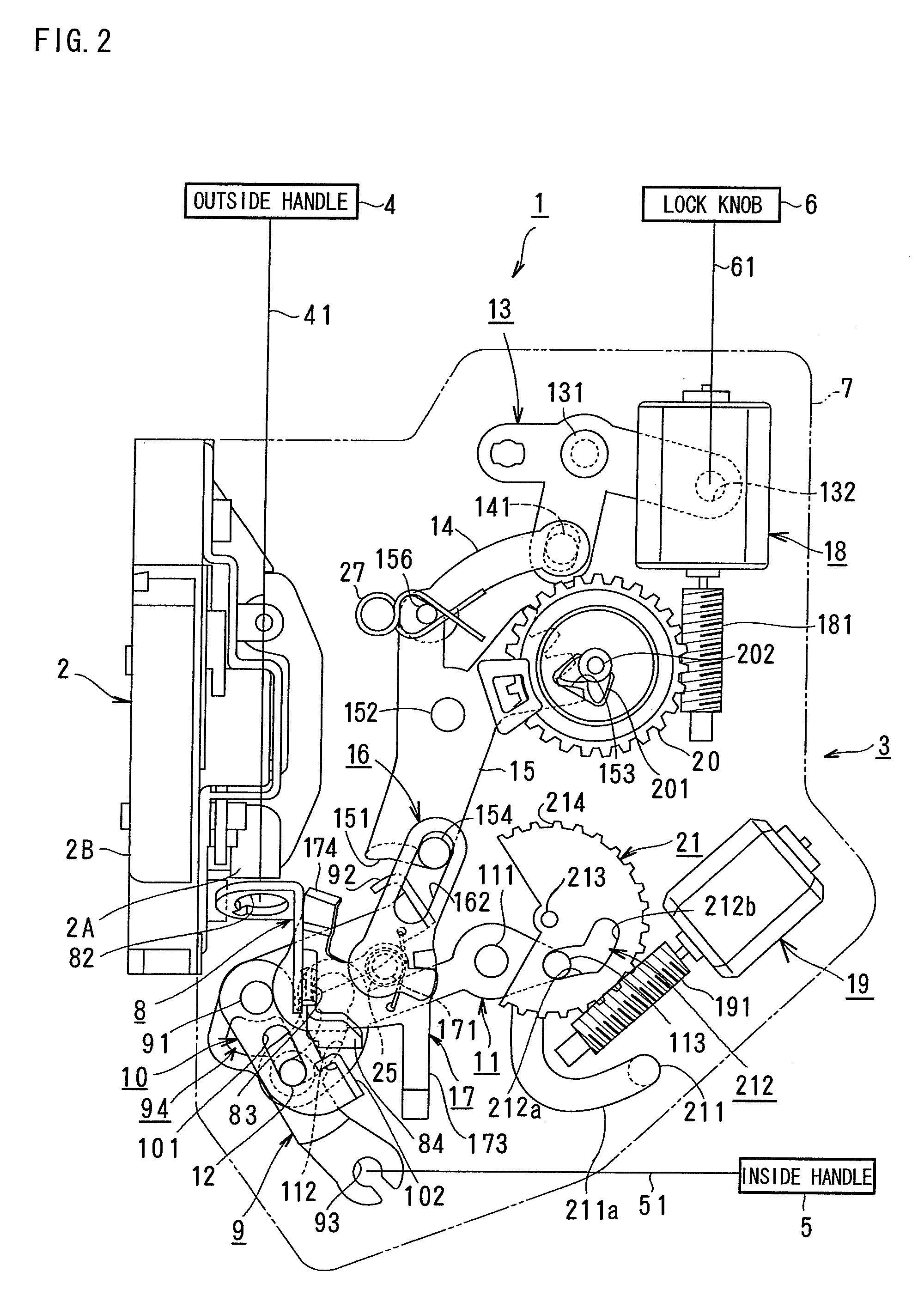
[0018]The right side in FIG. 2 and the left side in FIGS. 3-12 are a front of a motor vehicle, and the left side in FIG. 2 and right side in FIGS. 3-12 are a rear thereof. The front in FIG. 2 and the back in FIGS. 3-12 are the outside of the vehicle, and the back in FIG. 2 and the front in FIGS. 3-12 are the inside thereof.

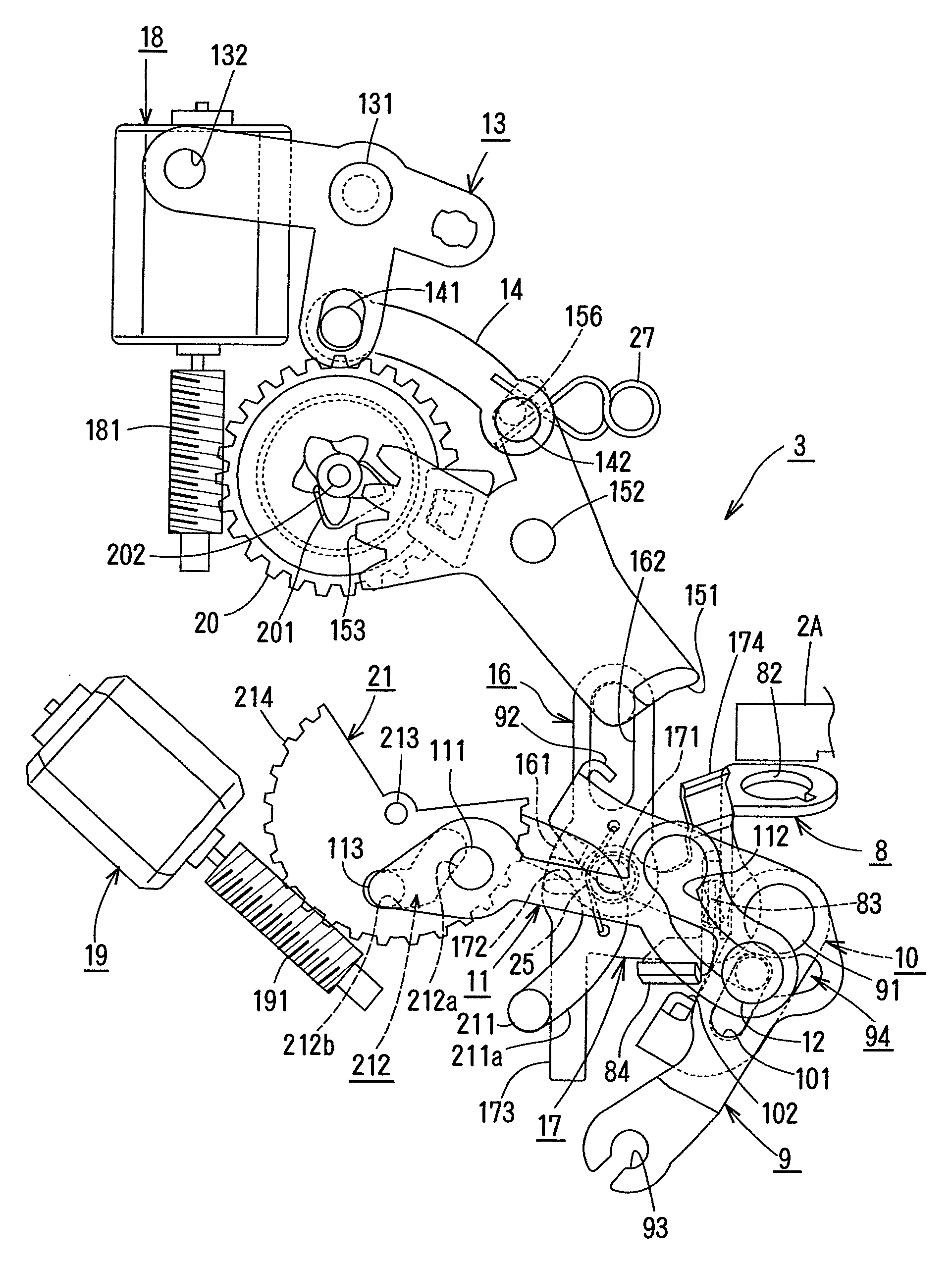
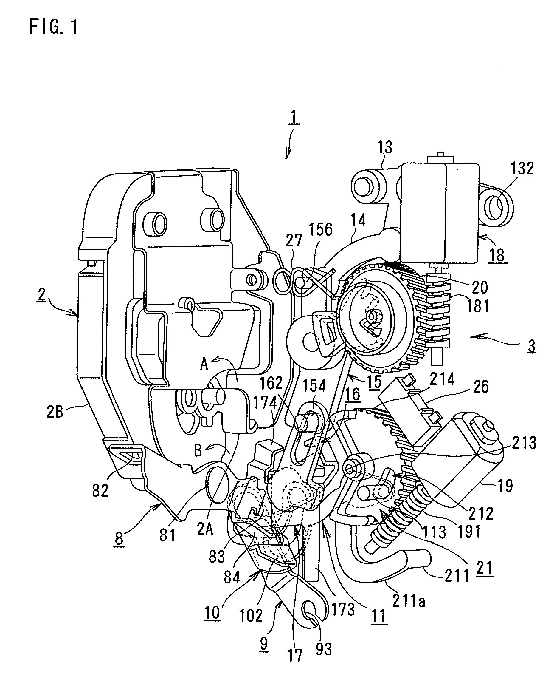
[0019]A door latch device 1 is disposed at the rear end of a rear door of the motor vehicle, and comprises an engagement portion 2 for holding the door in a closed position and an actuating portion 3 for actuating the engagement portion 2.

[0020]The door latch device 1 can be shifted among an unlocking state in FIG. 4 where the door can be opened with an outside handle 4 outside the vehicle or an inside handle 5 inside the vehicle, a locked state in FIGS. 2 and 3 where the door cannot be opened with the outside handle 4 but can be opened by double actions with the inside handle 5, a childproof locked state where the door can be opened with the outside handle 4 but ...


PUM


Abstract

A door latch device in a motor vehicle comprises an engagement portion including a latch which engages with a striker of a vehicle body. The door latch device comprises an inner lever connected to an inside handle, a lock lever connected to a lock knob on a door inside the vehicle, a subsidiary lever connected to the lock lever, a childproof lock lever, a motor and an actuating member driven by the motor to actuate the childproof lock lever. Childproof locking and a double locking can be carried out by the single motor.

Description

BACKGROUND OF THE INVENTION[0001]The present invention relates to a door latch device in a motor vehicle and particularly to a door latch device in a motor vehicle, the door latch device being placed in a double-lock state for deactivating unlocking of a lock knob inside the vehicle and a childproof lock state for deactivating an operation of an inside handle inside the vehicle.[0002]Besides a normal lock and unlock mechanism, a door latch device in a motor vehicle provides the structure that shifts a double lock state that prevents a lock knob inside the vehicle from being wrongfully unlocked or shifted to an unlocking state, and the childproof structure for preventing a door from opening even if an inside handle is operated by children in the vehicle intentionally or wrongfully for opening as disclosed in WO2006 / 099730A1, particularly in FIG. 5.[0003]However, in the door latch device therein, double lock is carried out by a double lock motor, while childproof locking is carried ou...

Claims


Application Information

Patent Timeline
Patent Type & Authority Applications(United States)
IPC IPC(8): E05B65/12E05B83/36B60J5/00E05B77/26E05B77/28E05B79/08E05B81/16
CPCE05B77/30E05B81/06E05B77/28E05B81/34E05B77/26E05B81/16Y10T70/5978Y10T292/1047Y10T292/1082
Inventor TAKAHASHI, AKIRAFARRIS, BRYAN
Owner MITSUI KINZOKU ACT
Why Eureka
Try Eureka