Device for coating a peripheral surface of a sleeve body

a technology of peripheral surface and sleeve body, which is applied in the direction of coating, foil printing, printing press parts, etc., can solve the problems of time-consuming production of masks, unsatisfactory high-quality printing and color registration, and the dimensional stability of masks, so as to achieve the effect of limited floor space requirements

Inactive Publication Date: 2009-10-01
AGFA NV
View PDF6 Cites 17 Cited by
  • Summary
  • Abstract
  • Description
  • Claims
  • Application Information

AI Technical Summary

Benefits of technology

[0019]In order to overcome the problems described above, preferred embodiments of the present invention provide a coating device that supports a wide range of sleeve types and sizes, and is capable of coating a single or a multitude of “uniform” layers of direct laser engraveable material. The term “uniform” can refer to surface properties, evenness, smoothness, homogeneity, coating formulation, etc. of the layer(s). A preferred embodiment provides a coating device with limited floor space requirements.

Problems solved by technology

Flexographic printing plate making according to the above described process has the disadvantage that the production of a mask is time consuming and that the dimensional stability of these masks with changing environmental temperature or humidity is unsatisfactory for high quality printing and color registration.
Moreover, the use of separate masks in flexographic printing plate production means additional consumables and chemistry, with a negative impact on economy and ecology aspects of the production process, which are far more a concern than the additional time required to make the masks.
As a matter of fact, in most cases plate exposure and plate development may turn out to be more time consuming than mask making.
This method still requires a developing step as in the case of previous methods and hence the improvement in efficiency for producing flexo printing plates is limited.
The post-curing step is required a.o. because of photopolymer unevenness of the coating process and the presence of a polymer bulge at the location where the coating stage was withdrawn from the sleeve when stopping the coating process.
The required grinding and polishing is a disadvantage of the Adless system.
The large floor space required, seen the horizontal position of the coating system, is also a disadvantage.

Method used


Image

  • Device for coating a peripheral surface of a sleeve body
  • Device for coating a peripheral surface of a sleeve body
  • Device for coating a peripheral surface of a sleeve body

Examples


embodiment details

Further Embodiment Details or Alternatives

Alternative Irradiation Stage

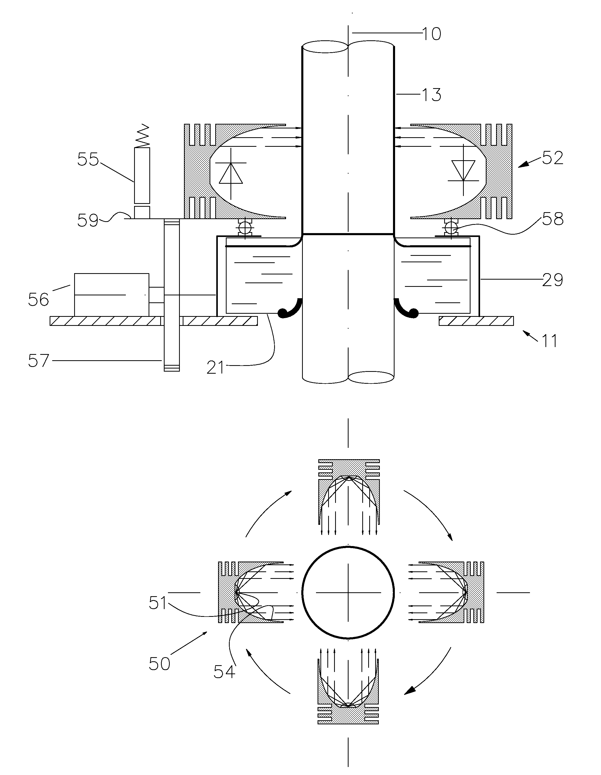
[0042]In the embodiments described above the irradiation source, e.g. an individual LED or an annular LED array, was linked to a corresponding collimating optics, e.g. a paraboloidal reflector respectively an annular collimating optics, and was considered as one assembly. In an alternative embodiment the optics may be omitted with the LED radiation source directly irradiating the peripheral surface of the coated sleeve. Rotation of the irradiation source may provide additional integration and averaging of the radiation energy. In another alternative embodiment a non-rotating annular collimating optics may be combined with a rotating radiation source. In this configuration, the radiation source orbits between the peripheral surface of the sleeve core and the annular collimating optics.

Radiation Lock

[0043]From Eq. 1 we know that the viscosity of the coating formulation is an important parameter in controlling the t...


PUM

PropertyMeasurementUnit
wavelengthsaaaaaaaaaa

Abstract

A coating device for coating a peripheral surface of a sleeve body with a coating formulation includes a vertical support column for supporting a sleeve body in a vertical position coaxial with a coating axis, a carriage slideable along the vertical support column, and an annular coating stage attached to the carriage and moveable therewith for containing the coating formulation and for coating a layer of the coating formulation onto the peripheral surface of the sleeve body during a sliding movement of the carriage along the vertical support column. The coating device includes an irradiation stage that is arranged to be moveable with the annular coating stage and to provide radiation to at least partially cure the layer of coating formulation onto the peripheral surface so as to prevent flow off of the coating formulation.

Description

CROSS-REFERENCE TO RELATED APPLICATIONS[0001]This application is a 371 National Stage Application of PCT / EP2007 / 059807, filed Sep. 18, 2007. This application claims the benefit of U.S. Provisional Application No. 60 / 846,924, filed Sep. 25, 2006, which is incorporated by reference herein in its entirety. In addition, this application claims the benefit of European Application No. 06120823.7, filed Sep. 18, 2006, which is also incorporated by reference herein in its entirety.BACKGROUND OF THE INVENTION[0002]1. Field of the Invention[0003]The present invention relates to an apparatus and a method for coating a sleeve body with a single or a multitude of uniform layers of a coating formulation.[0004]More specifically the invention is related to a coating device and method of coating wherein an irradiation stage is moveable with a coating stage. The irradiation stage at least partially cures the coated layer applied by the coating stage.[0005]2. Description of the Related Art[0006]Flexog...

Claims


Application Information

Patent Timeline
Patent Type & Authority Applications(United States)
IPC IPC(8): B41N1/16B05C9/14B05D3/06B41F31/00
CPCB05C3/10B05C5/0208B05C9/14B41C1/182B05D3/067B05D2254/02B05D1/18
Inventor LEENDERS, LUCMUES, WILLEMDUPREZ, JACKIEVERHOEST, BARTVANDEN WYNGAERT, HILBRANDDAEMS, EDDIEVANMAELE, LUC
Owner AGFA NV
Why Eureka
Try Eureka