Generating hydroenergy

a technology of hydropower and hydropower, applied in the direction of conventional hydropower generation, dynamo-electric machines, emission reduction for energy storage, etc., can solve the problems of difficult control, large amount of electricity storage, and fluctuation of electricity demand

Inactive Publication Date: 2012-03-08
AALTONEN JANNE +1
View PDF6 Cites 10 Cited by
  • Summary
  • Abstract
  • Description
  • Claims
  • Application Information

AI Technical Summary

Benefits of technology

[0027]In an embodiment of the disclosure, the hydroenergy generating plant comprises a reversible turbine / generator assembly arranged as both the removal means and the energy recovering means. This means that water is led into the reservoir and water is removed from the reservoir via the same assembly capable of functioning both as a pump or a turbine. In one embodiment a pump unit, a generator unit and inlet means needed are all combined into a pump / generator unit. A reversible turbine / generator assembly can be a so-called double stage regulated pump-turbine, which gives the possibility to utilise very high head for pumped storage, hence providing higher energy and efficiency, but also variable speed drive allowing wider grid support such as frequency regulation in pumping mode as well as larger operation window, hence yielding better economics, flexibility and reliability. In one embodiment, there is a separate pump for emptying water from the storage unit. The energy can be generated via vertical or horizontal Kaplan type turbine allowing good efficiency with low head. In an alternate embodiment a Kaplan type turbine is used also for pumping.
[0031]The aspects of the disclosed embodiments provide an efficient and environmentally friendly technology for storing energy in new regions. There is no need for great natural differences in altitude such as rapids or mountain lakes.

Problems solved by technology

As a general rule, it is hard to store large amounts of electricity.
However, the demand for electricity varies over time.
Common sources of alternative energy such as, for example, solar energy and wind energy, produce energy depending on the weather conditions and can be unpredictable and difficult to control.
Although production of hydroelectricity can be considered as virtually non-polluting and renewable, building of new facilities is often considered as a great stress to nature.
Also fluctuations in the water level in reservoirs normally have negative effects to the ecosystem.
A problem with such a system is control of buoyancy.

Method used


Image

  • Generating hydroenergy
  • Generating hydroenergy
  • Generating hydroenergy

Examples


example

[0078]Cone smaller diameter: 300 m->R=150 m, Cone bigger diameter: 290 m->r=145 m, Cone height: 50 m

[0079]Fd=pi*50 m*1000 kg / m3*9.81 m / s2*(⅓*(R̂2+Rr+r̂2)−R̂2)=−1 142,872,137 N=−1,142,872 kN or −116,501 t (negative value, i.e. cone is pushed down, in addition comes the weight of the structure).

[0080]Force can also be calculated as t / m on perimer: Fd / 2*pi*R=123 t / m

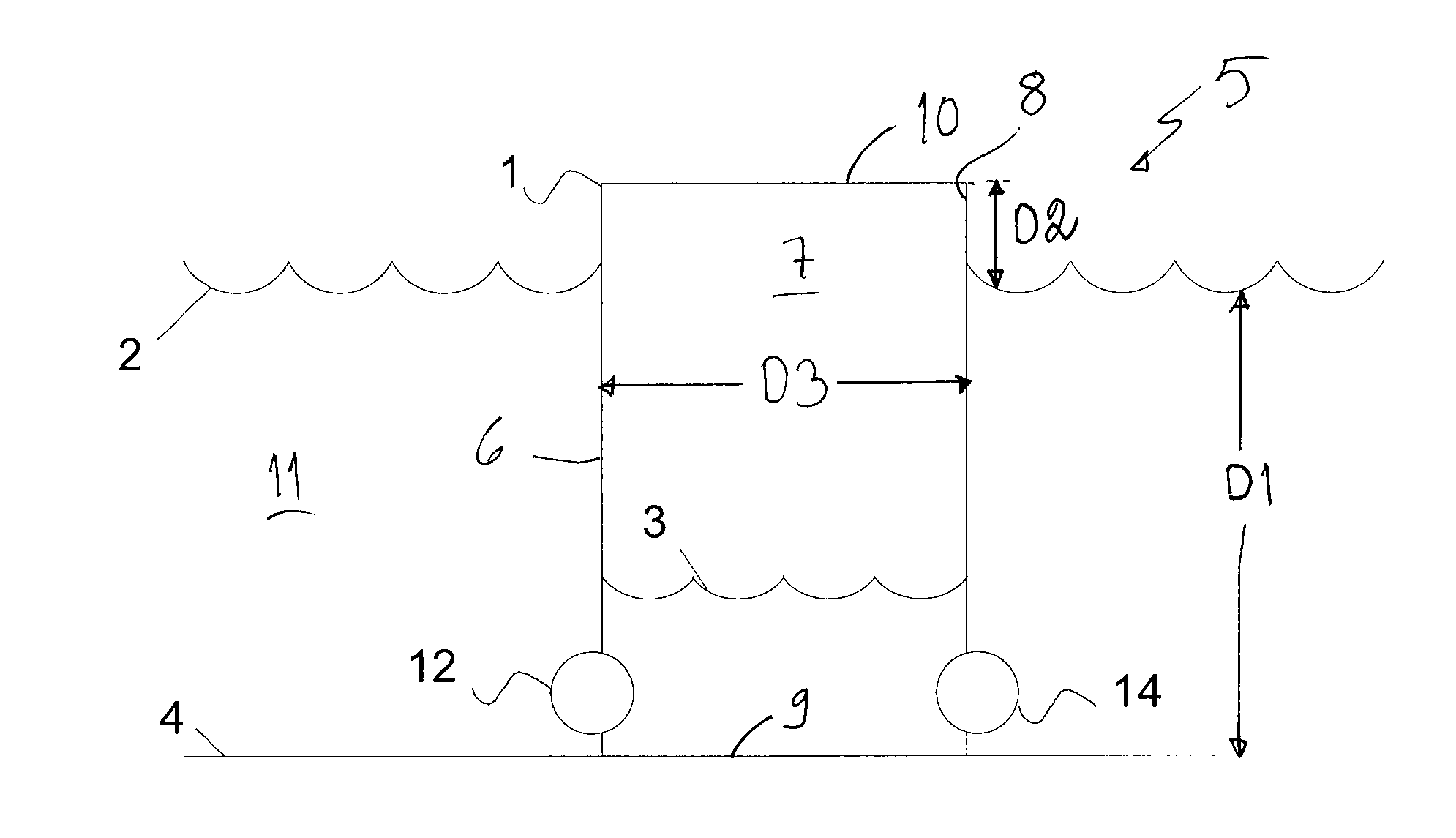
[0081]Sea water pressure results to large downwards force keeping the structure firmly in the sea bed 4 when empty from water 3. This type of structure which brings added downward force towards sea bed is beneficial since the total structure is more robust against storms and waves. In practice, the structure of this embodiment could be cylinder like with smaller diameter in the top part of the structure than in the lower part of the structure. Walls 6 of reservoir 7 are aligned in a way that some of the force resulting from pressure difference between inside and outside of reservoir is directed downwards.


PUM


Abstract

A method of recovering energy from the potential energy of water in a body of water includes providing a reservoir at least partly below a surface of a body of water, leading water from the body of water in the reservoir, and storing potential energy by removing water from the reservoir. A hydroenergy plant recovers energy from the water while leading the water into the reservoir using a turbine and an electric generator coupled to the turbine.

Description

CROSS-REFERENCE TO RELATED APPLICATIONS[0001]This application claims priority to and the benefit of European Application No. 10151095.6, filed Jan. 19, 2010, the disclosure of which is incorporated by reference herein in its entirety.BACKGROUND[0002]1. Field[0003]The aspects of the disclosed embodiments relate to a new way of recovering energy from the potential energy of water in a body of water. Particularly, the aspects of the disclosed embodiments relate to a method of generating hydroenergy, a hydroenergy generating plant, a use of the hydroenergy generating plant and a method of storing potential energy of water.[0004]2. Brief Description of Related Developments[0005]As a general rule, it is hard to store large amounts of electricity. Therefore energy is normally consumed at the same time it is produced. However, the demand for electricity varies over time. Typically there is lower demand for electricity during night time than day time. Common sources of alternative energy suc...

Claims


Application Information

Patent Timeline
Patent Type & Authority Applications(United States)
IPC IPC(8): F03B13/06
CPCF03B13/06F03B13/10Y02E60/17Y02E10/20Y02E10/22F03B17/00Y02E60/16Y02P90/50
Inventor AALTONEN, JANNEAARNIO, MARKUS
Owner AALTONEN JANNE
Why Eureka
Try Eureka