Electrical connection device

a technology of electrical connection and joint portion, which is applied in the direction of coupling device connection, semiconductor/solid-state device details, semiconductor devices, etc., can solve the problems of difficulty in equal or general application of load to the joint portion, and achieve the effect of convenient pressing

Inactive Publication Date: 2013-08-06
AISIN AW CO LTD
View PDF13 Cites 10 Cited by
  • Summary
  • Abstract
  • Description
  • Claims
  • Application Information

AI Technical Summary

Benefits of technology

[0008]According to the first aspect, the joint portion is supported by the support body via the crossover portions and the supported portions. Therefore, the joint portion can be pressed against the joint surface of the electrode member by applying a force in the pressing direction to the support body without directly applying a force to the joint portion. At this time, because the joint portion is supported by the support body on both sides in the extending direction, a load is applied to the joint portion from both sides in the extending direction. The support body is formed to integrally support the supported portions on both sides of the joint portion. Thus, it is easy to press the support body such that a load is applied to the joint portion equally or generally equally from both sides in the extending direction, and as a result, it is easy to bring the joint portion into good surface contact with the joint surface of the electrode member.
[0022]According to the seventh aspect, a load received by the support body from the connection member while being pressed against the electrode member can be dispersed within the support body, which enables the connection member to be supported by the support body over a wide range. Hence, it is possible to prevent the support body from being significantly locally deformed while being pressed against the electrode member, which makes it further easier to press the support body such that a load is applied to the joint portion equally or generally equally from both sides in the extending direction.

Problems solved by technology

In such configurations, it is be difficult to apply a load to the joint portion equally or generally equally from both sides in the extending direction without a complicated configuration.

Method used


Image

  • Electrical connection device
  • Electrical connection device
  • Electrical connection device

Examples


Embodiment Construction

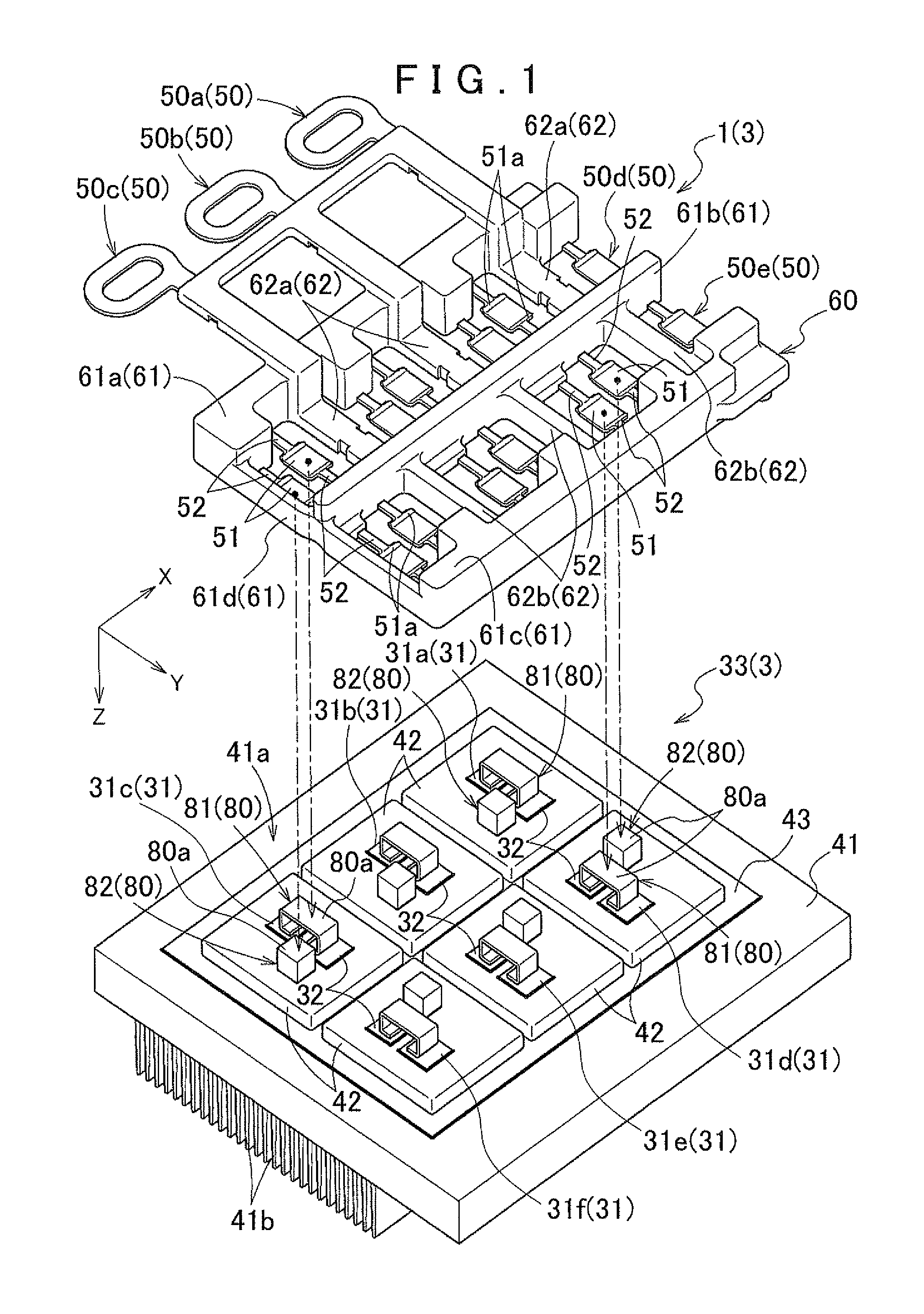
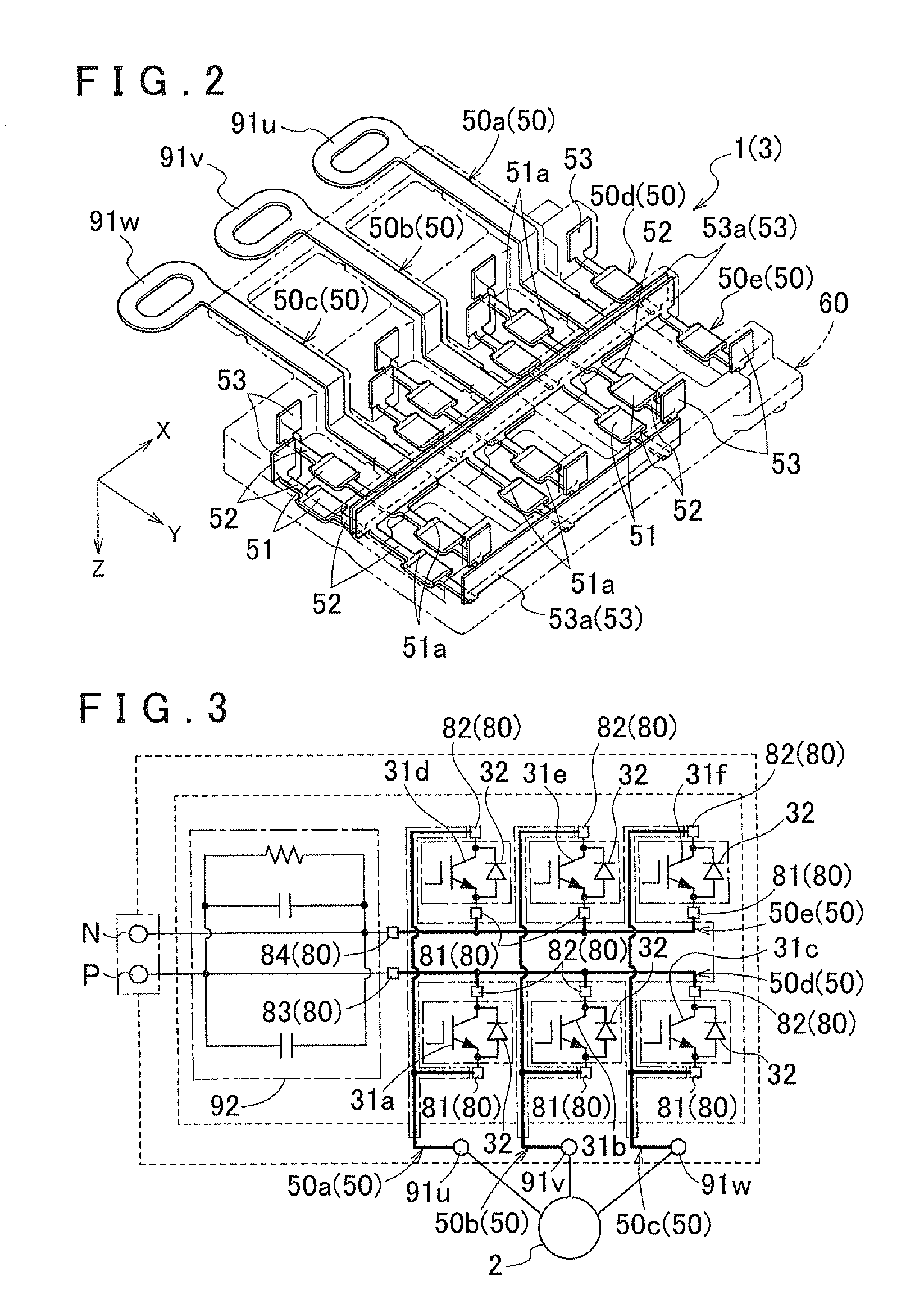
[0029]An electrical connection device according to an embodiment of the present invention will be described with reference to the drawings. Here, the electrical connection device according to the present invention is applied to a bus bar module 1 forming an inverter module 3 which controls a rotary electric machine 2. As shown in FIG. 1, the bus bar module 1 includes bus bars 50 having joint portions 51. The joint portions 51 are joined to electrode members 80 provided in a switching module 33 in the state of being pressed against the electrode members 80. In such a configuration, the bus bar module1 according to the embodiment is characterized in the shape of the bus bars 50 and the configuration of a support body 60 that supports the bus bars 50. The configuration of the bus bar module 1 according to the embodiment will be described below in the order of “Overall Configuration of Inverter Module” and “Configuration of Bus Bar Module”.

[0030]In the embodiment, the bus bar module 1 a...


PUM


Abstract

An electrical connection device configured with a conductive connection member having a joint portion joined to an electrode member while being pressed against the electrode member in a pressing direction. An insulating support body supports the connection member such that the connection member includes the joint portion which is formed in a flat plate shape and is brought into surface contact with a joint surface of the electrode member. Crossover portions sandwich the joint portion and extend toward both sides along a predetermined extending direction. Supported portions are provided at respective end portions, opposite the joint portion, of the crossover portions on both sides. The support body is disposed at least on both sides of the joint portion in the extending direction and spaced apart from the joint portion, and formed to integrally support the supported portions on both sides of the joint portion.

Description

INCORPORATION BY REFERENCE[0001]The disclosure of Japanese Patent Application No. 2010-196633 filed on Sep. 2, 2010 including the specification, drawings and abstract is incorporated herein by reference in its entirety.BACKGROUND OF THE INVENTION[0002]The present invention relates to an electrical connection device that includes a conductive connection member having a joint portion to be joined to an electrode member in the state of being pressed against the electrode member in a predetermined pressing direction, and an insulating support body that supports the connection member.Description of the Related Art[0003]In recent years, hybrid vehicles and electric vehicles including a rotary electric machine as a drive power source have been drawing attention from the viewpoint of conserving energy and reducing the load on the environment. In such hybrid vehicles and electric vehicles, an inverter device controls a current flowing through the rotary electric machine. The inverter device ...

Claims


Application Information

Patent Timeline
Patent Type & Authority Patents(United States)
IPC IPC(8): H01R24/00
CPCH01L23/49861H01L23/5385H01L25/072H01L2924/1305H01L2924/014H01L2224/83447H01L2224/83424H01L2224/73263H01L2924/1203H01L2924/13055H01L2924/13091H02M7/003H01L2224/06181H01L2224/40137H01L24/06H01L24/29H01L24/32H01L24/37H01L24/40H01L24/73H01L24/83H01L2224/291H01L2224/32245H01L2224/37124H01L2224/37147H01L2924/00H01L2224/83801H01L2924/00014
Inventor SUZUKI, TOMOYUKI
Owner AISIN AW CO LTD
Why Eureka
Try Eureka