Valve locking device

a locking device and valve technology, applied in the direction of valve details, valve member-seat contacts, preventing unauthorised/accidental actuation, etc., can solve the problems of preventing adequate ventilation, prone to damage or injury, and cumbersome use of hoods

Inactive Publication Date: 2006-10-10
SHUTER CHARLES FREDERICK THOMAS
View PDF7 Cites 14 Cited by
  • Summary
  • Abstract
  • Description
  • Claims
  • Application Information

AI Technical Summary

Benefits of technology

[0019]In a second aspect, the present invention provides a combination of a valve locking device of the first aspect of the present in

Problems solved by technology

In many industrial installations valves are used in circumstances where their incorrect operation could lead to accidents resulting in serious damage or injury.
For example, dosing a valve may prevent adequate ventilation.
However, some ball valves require rotation of an operating spindle through 180 de

Method used


Image

  • Valve locking device
  • Valve locking device
  • Valve locking device

Examples


Embodiment Construction

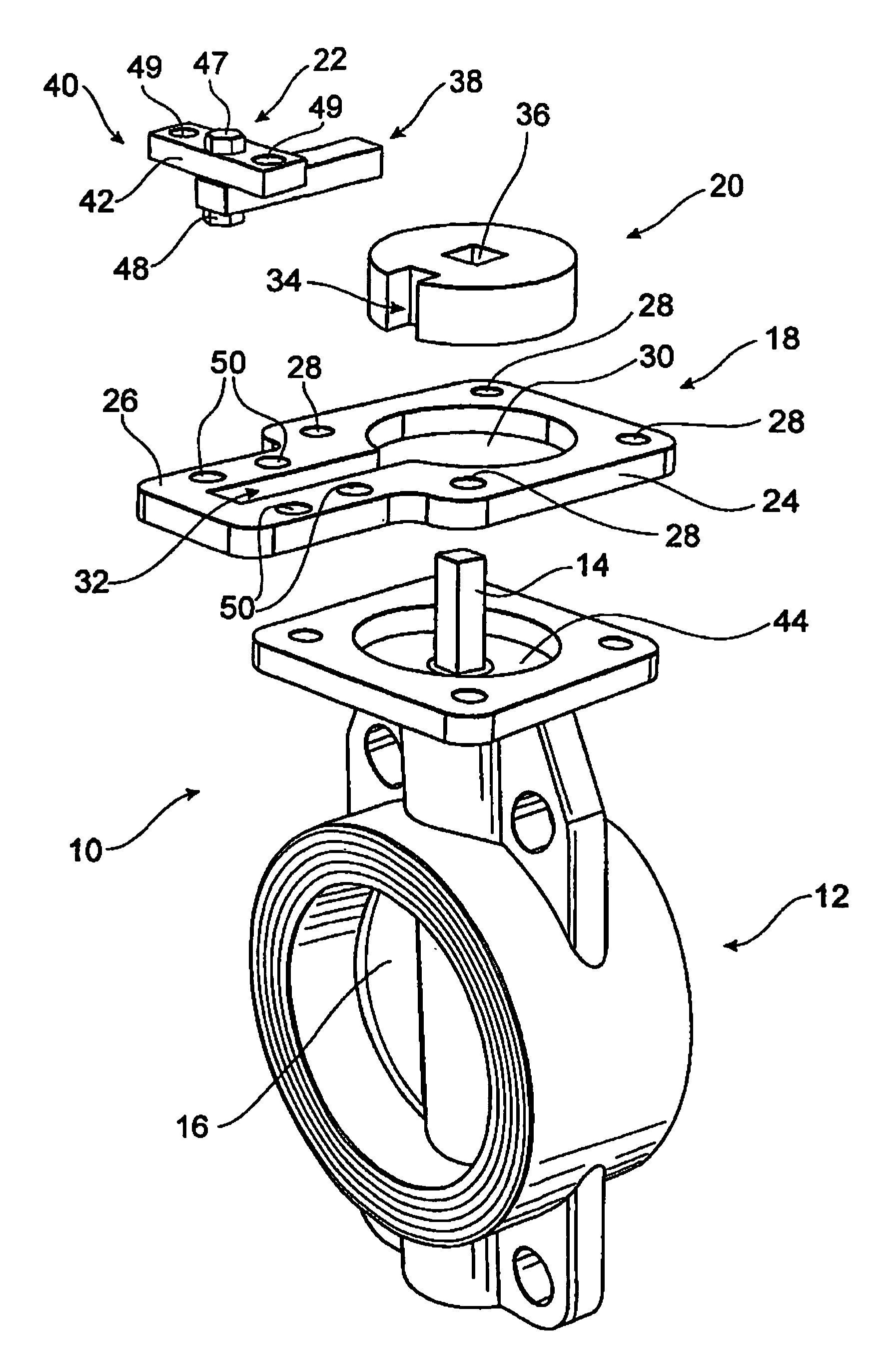
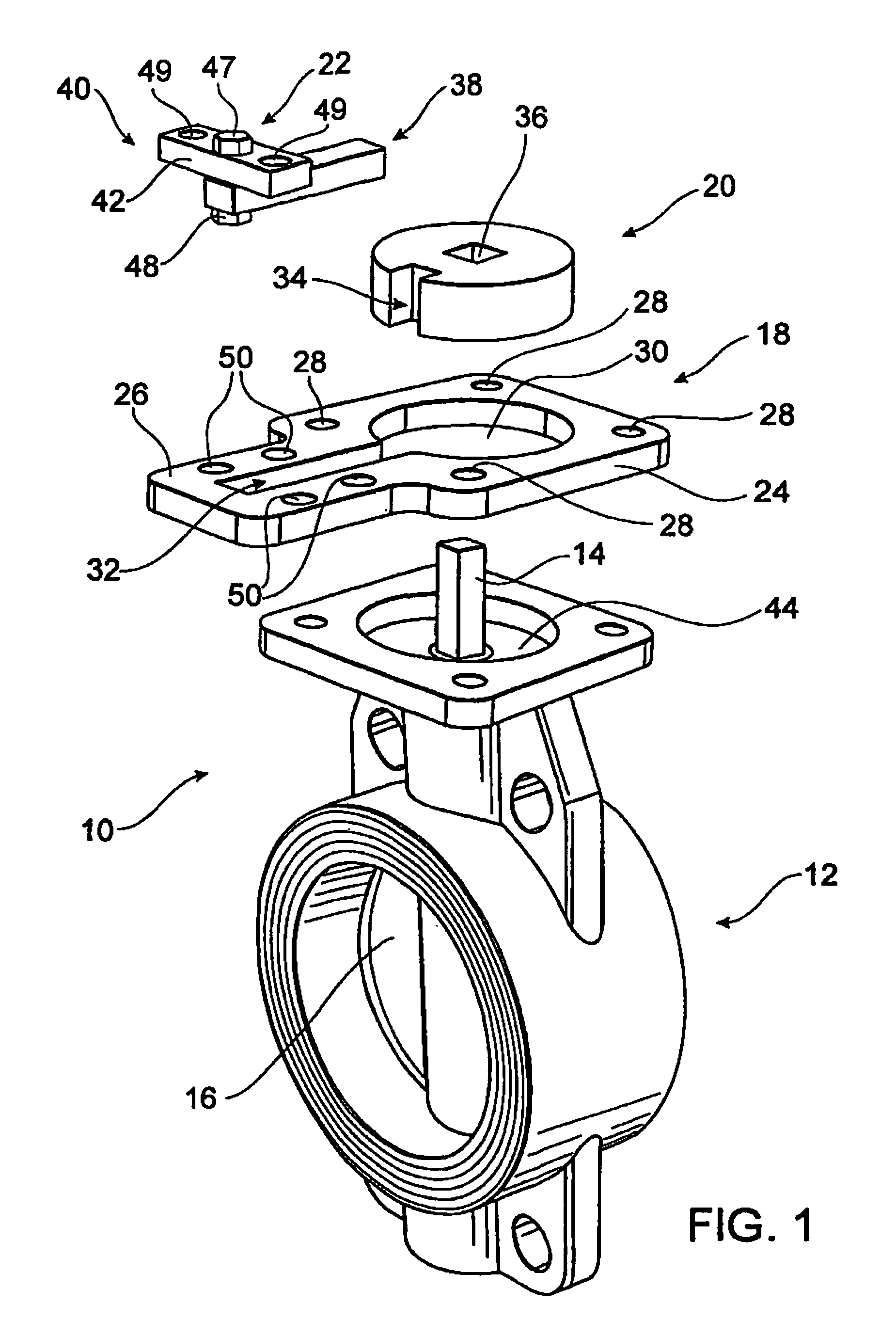
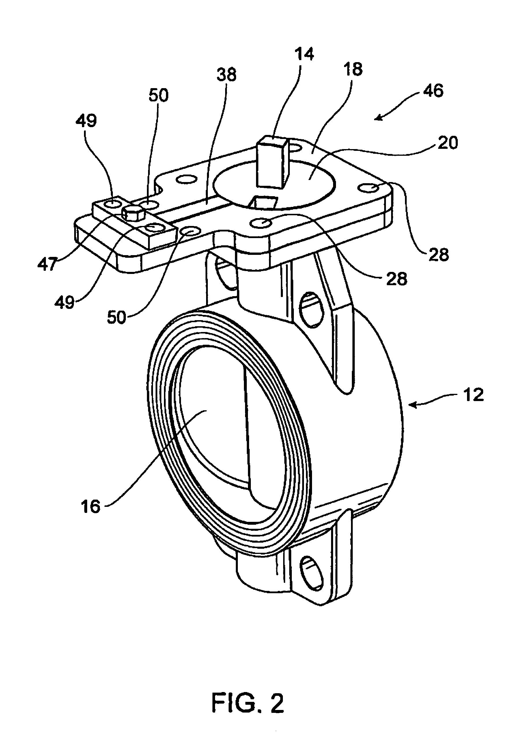
[0027]Referring to FIG. 1, a butterfly valve 12 having an end 10, from which a spindle 14 extends, is typically bolted to a valve actuator (not shown). The valve actuator functions to rotate the spindle 14 of the butterfly valve 12. Rotation of the spindle 14 results in movement of a valve 16 of the butterfly valve 12 between open and closed positions.

[0028]The unassembled valve lock of FIG. 1, which provides an example of the valve locking device, comprises a plate 18, a cylindrically shaped spindle receiving disc 20 and a key 22. The plate 18, spindle receiving disc 20 and key 22 provide an example of the intermediate member, spindle attachment member and engagement member respectively. One end 24 of the plate 18 is generally square in shape while the other end 26 of the plate 18 is generally rectangular in shape. However, It will be appreciated by a person skilled in the relevant field that depending on the shape of a valve and / or valve actuator, a plate could be shaped different...


PUM


Abstract

A valve locking device comprising an intermediate member (18) mountable between a valve body and valve actuator and securable to said valve body and/or actuator; a stem attachment member (20) attachable to and rotatable with a valve stem (14) and contained at least partially within said intermediate member, and an engagement member (22) movably located within said intermediate member for selective engagement with said stem attachment member; whereby in use, engagement between said engagement member and said stem attachment member prevents rotation of said stem attachment member, thus preventing rotation of said valve stem to operate the valve.

Description

FIELD OF THE INVENTION[0001]The present invention relates to valve locking devices for locking a valve in a particular position to prevent it moving from an open position to a closed position or vice versa. In particular, the present invention relates to a valve locking device which is mountable between a valve and valve actuator.BACKGROUND TO THE INVENTION[0002]In many industrial installations valves are used in circumstances where their incorrect operation could lead to accidents resulting in serious damage or injury. For example, many factories utilise pressure vessels which need to be entered by workers for maintenance and / or repair. It is essential that valves controlling supply of fluid under pressure to such vessels are locked in the shut or closed position when such maintenance or repair is taking place. In other situations it may be important for safety purposes that a valve is not closed. For example, dosing a valve may prevent adequate ventilation.[0003]Typically butterfl...

Claims


Application Information

Patent Timeline
IPC IPC(8): F16K35/00F16K35/02
CPCF16K35/022Y10T137/7256
Inventor SHUTER, CHARLES FREDERICK THOMAS
Owner SHUTER CHARLES FREDERICK THOMAS
Why Eureka
Try Eureka