
Vacuum insulator in a storehouse and methods of making and using the same

a vacuum insulator and storehouse technology, applied in manufacturing tools, domestic cooling devices, lighting and heating devices, etc., can solve the problems of excessive use of heat insulating walls, difficulty in allowing the storehouse to reach a desired temperature, and excessive time taken to reach a target temperature, so as to improve the heat insulating effect and improve the thermal conductivity. , the effect of high vacuum

Active Publication Date: 2021-01-26
LG ELECTRONICS INC
View PDF47 Cites 12 Cited by
  • Summary
  • Abstract
  • Description
  • Claims
  • Application Information

AI Technical Summary

Benefits of technology

The present invention improves the heat insulating effect due to high vacuum and improves the surface contact between components, which leads to improved heat transfer performance. The thermoelectric module is placed in the vacuum space without needing a separate coupling operation, such as by bolt. The heat diffusion module and heatsink are securely coupled to the components outside the vacuum space to maintain reliable coupling and maximize thermal conductivity. The thermal interface module made of metal material with low outgassing property is intervened between the components to further improve heat conduction performance. The electric wire disposed in the vacuum space is peeled off to reduce outgassing, and a sheath is placed on the electric wire to prevent short-circuiting. The thermal interface module prevents the deformation of the plate by high vacuum pressure and ensures optimal heat conduction performance.

Problems solved by technology

When the storehouse installed in the vehicle uses an existing air conditioning system installed in the vehicle, it is difficult to allow the storehouse to reach a desired temperature, or a time taken to reach a target temperature is excessively long.
Thus, there is a limitation that a thick heat insulating wall is used, and sufficient heat insulating performance is not obtained even if the thick heat insulating wall is used.
However, according to the above-described related art, sufficient vacuum may not be obtained.
Thus, there is a problem that the sufficient heat insulating effect is not obtained.
Also, since it is difficult to improve the performance of the thermoelectric module, a large cooling effect may not be obtained when compared to the consumed electric energy.

Method used


Image

  • Vacuum insulator in a storehouse and methods of making and using the same
  • Vacuum insulator in a storehouse and methods of making and using the same
  • Vacuum insulator in a storehouse and methods of making and using the same

Examples


Embodiment Construction

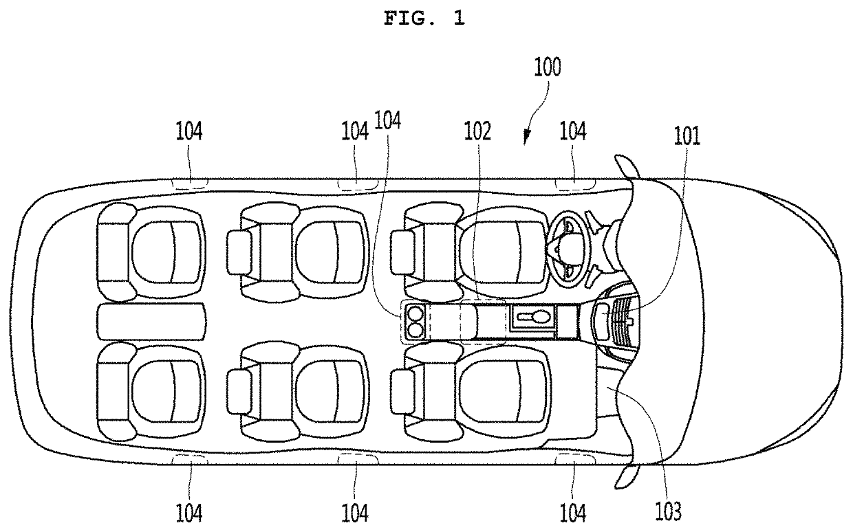
[0049]FIG. 1 is a plan view of a vehicle according to an embodiment.

[0050]At least one or more storehouses may be provided in a vehicle 100 according to an embodiment. For example, the storehouse may be at least one of a console box storehouse 101 mainly used by a driver, an armrest storehouse 102 disposed in an armrest mainly used by the driver or an assistant driver, a globe box storehouse 103 disposed in a globe box mainly used by the assistant driver, a passenger side storehouse 104 mainly used by a passenger in the rear seat, and a door side storehouse 104 provided in a door of the vehicle. The storehouses 101, 102, 103, and 104 may perform a function of at least one of cold storage and warm storage or a function of a cooling and heating cabinet.

[0051]Hereinafter, in description according to embodiments, the cold stage will be mainly described. However, it may be understood that a case in which it is written as the cold storage / warm storage refers to all of the cold storage, th...


PUM


Abstract

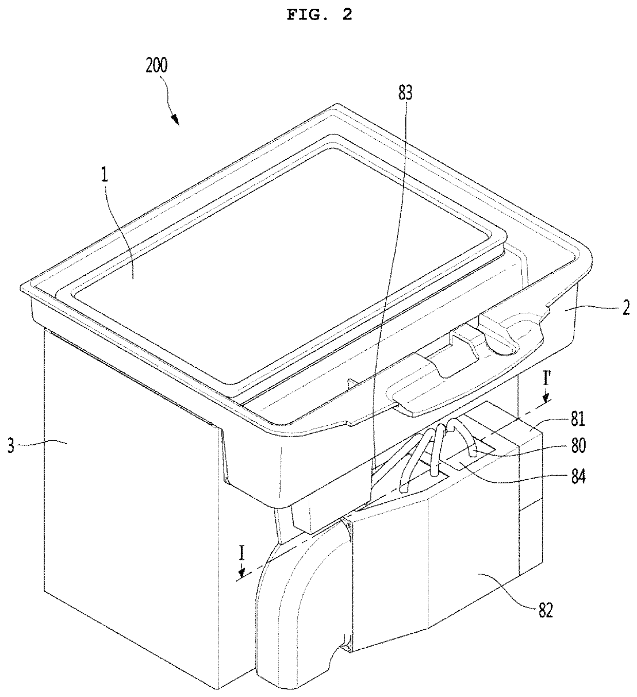
Disclosed is a vacuum insulator comprising: a heat diffusion block placed in a third space; a thermoelectric module coming into contact with the heat diffusion block so as to exchange heat therewith, and placed in the third space; and a heat sink exchanging heat with the thermoelectric module and placed in a first space or a second place. According to the present invention, high heat-insulation performance and heat-transfer performance can be obtained.

Description

CROSS-REFERENCE TO RELATED PATENT APPLICATIONS[0001]This application is a U.S. National Stage Application under 35 U.S.C. § 371 of PCT Application No. PCT / KR2016 / 014306, filed Dec. 7, 2016, which claims priority to Korean Patent Application No. 10-2015-0179480, filed Dec. 15, 2015, whose entire disclosures are hereby incorporated by reference.TECHNICAL FIELDBackground Art[0002]In some cases, a vehicle is equipped with a storehouse to store simple beverage cans or a small amount of food. The storehouse is mainly installed in an internal space such as an armrest so that a driver conveniently eats the beverage can or food. As the storehouse is installed in a luxury vehicle, an image of the vehicle is enhanced, and user's convenience is more improved.[0003]When the storehouse installed in the vehicle uses an existing air conditioning system installed in the vehicle, it is difficult to allow the storehouse to reach a desired temperature, or a time taken to reach a target temperature is e...

Claims


Application Information

Patent Timeline
Patent Type & Authority Patents(United States)
IPC IPC(8): B60N3/10B60R7/04F25B21/04F25D19/00F25D23/08F25D23/02F25D23/06F25B21/02
CPCB60N3/104B60R7/04F25B21/02F25B21/04F25D19/00F25D19/006F25D23/02F25D23/06F25D23/065F25D23/08F25B2321/023F25B2321/025F25D2201/14B65D81/38B65D81/3806B25D9/00
Inventor JUNG, WONYEONGKANG, MYOUNGJUYOUN, DEOKHYUNLEE, SUNGSUBKIM, SORAKIM, DAEWOONGLEE, JANGSEOK
Owner LG ELECTRONICS INC
Learn More