Broadband Amplifying Device

Inactive Publication Date: 2009-10-01
THALES SA
View PDF5 Cites 20 Cited by
  • Summary
  • Abstract
  • Description
  • Claims
  • Application Information

AI Technical Summary

Benefits of technology

[0024]The advantage of the solution is that it allows an alignment between amplifiers over a broad frequency band, which makes it possible to use

Problems solved by technology

Such multibeam or multispot coverages make links with small ground terminals possible but they pose the problem of managing the onboard capacities and more particularly the allocation of the received channels to the transmitted beams according to:the different traffic densities,changes in traffic densities over time.
However, this architecture is not flexible and combines channeled amplification (one amplifier per channel and recombination of the channels through t

Method used


Image

  • Broadband Amplifying Device
  • Broadband Amplifying Device
  • Broadband Amplifying Device

Examples


Embodiment Construction

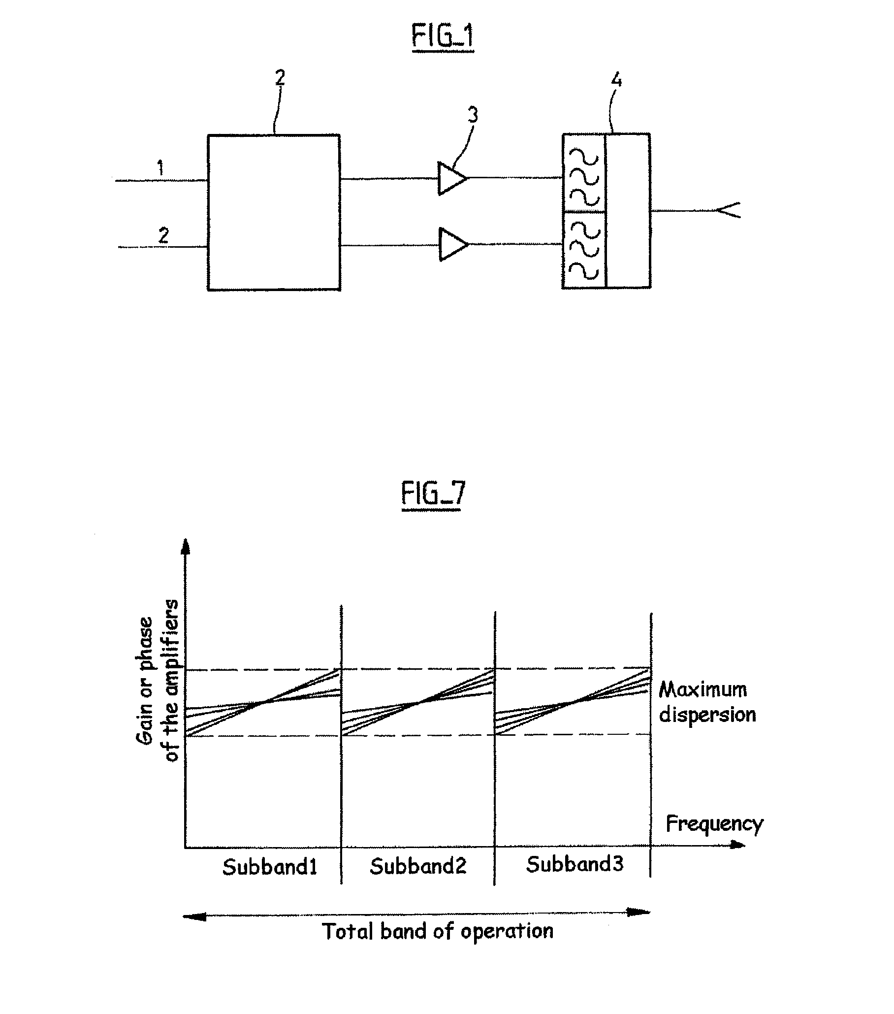
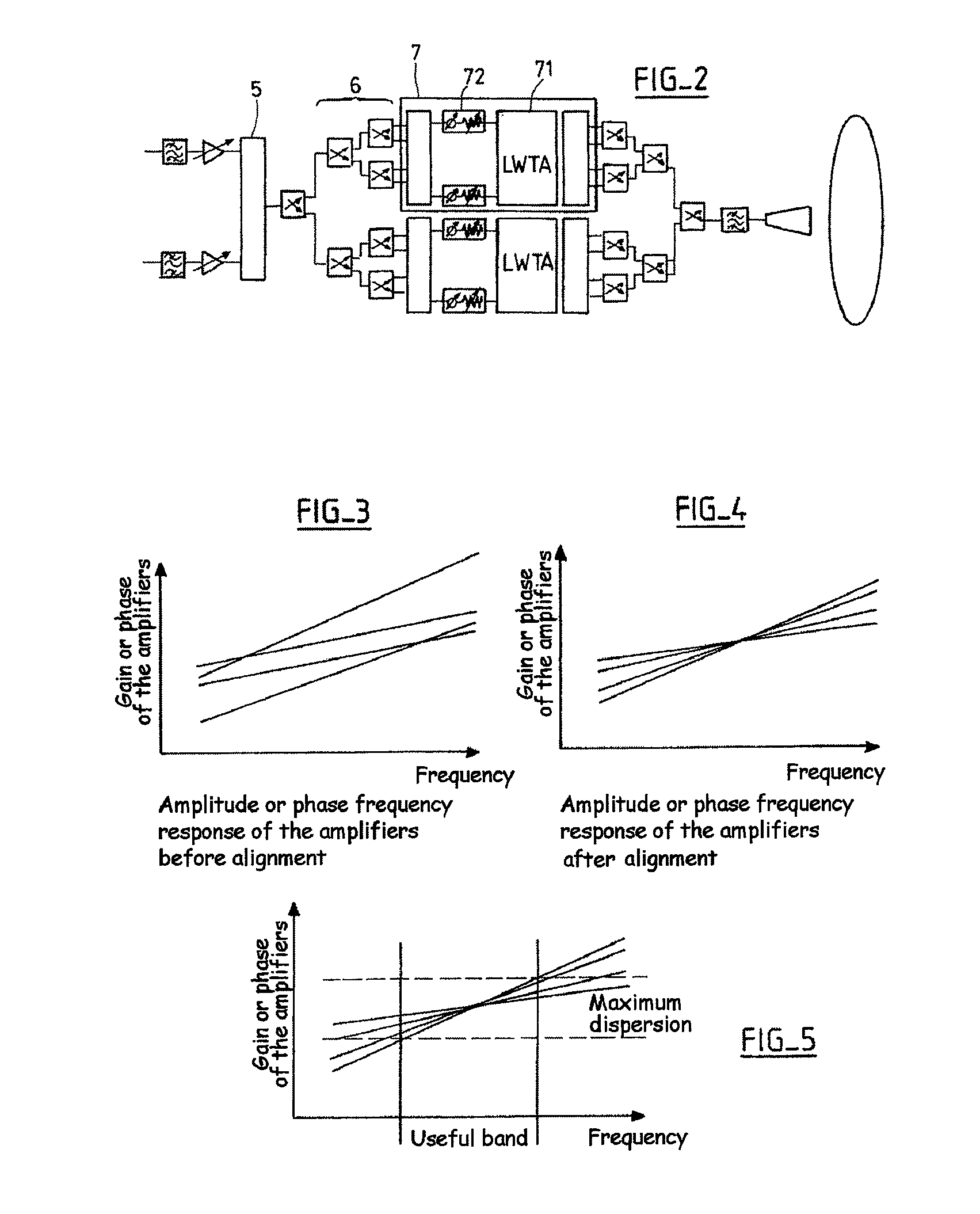
[0034]FIGS. 1, 2, 3, 4 and 5 have already been described with reference to the prior art.

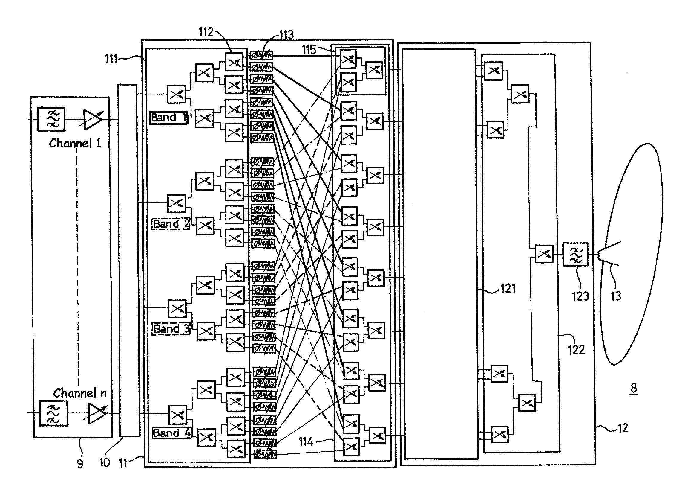
[0035]FIG. 6 represents a device 8 suitable for amplifying and flexibly distributing n signals C1 (channel 1) to Cn (channel n) of input signals to an output signal corresponding to a beam.

[0036]The device 8 comprises:[0037]an input section 9 with n inputs and n outputs,[0038]a combiner 10 with n inputs and q outputs (q=4 in the present embodiment),[0039]an amplifier amplitude / phase adjustment unit 11,[0040]a block 12 for power amplification,[0041]a transmission antenna 13.

[0042]The input section 9 receives the n uplink transmission channels C1 to Cn each corresponding to one transmission channel. The input section 9 then performs the following operations:[0043]appropriate frequency conversion of each of the n transmission channels C1 to Cn, filtering, and gain control,[0044]delivery of the n transmission channels to the respective n inputs of the frequency band combiner 10.

[0045]The combiner 10...


PUM


Abstract

The present invention relates to an amplification device for a satellite in order to amplify a plurality of n transmission channels to an output corresponding to a beam, the device comprising:
  • frequency band combining means comprising n inputs in order to receive the n transmission channels and q outputs in order to supply respectively the channels grouped together within q frequency bands,
  • a power amplification unit including p active amplifiers in parallel for the distributed amplification of the n channels,
  • gain and phase adjustment means corresponding to the p power amplifiers on the q frequency bands.

Description

BACKGROUND OF THE INVENTION[0001]The present invention relates to an amplification device for a satellite suitable for flexibly distributing a plurality of received transmission channels to an output beam signal.[0002]In the usual space mission situation, the change in satellite transmissions to users equipped with transmit / receive terminals of reduced capacity and of small dimension requires an increase in the quality of reception of the onboard segment and an increase in the power of the signals retransmitted to the ground. These performance increases are obtained by increasing the onboard antenna gains, which can be achieved only by reducing the dimensions of their ground coverages. These coverage reductions require, in order to cover a particular geographic coverage zone on the ground, generating several beams or spots in order to sample the geographic zone. Such multibeam or multispot coverages make links with small ground terminals possible but they pose the problem of managin...

Claims


Application Information

Patent Timeline
IPC IPC(8): H03F1/00
CPCH04B7/18515
Inventor VOISIN, PHILIPPEBELMONT, JACQUES
Owner THALES SA
Why Eureka
Try Eureka