Twistable ring speaker control

a speaker control and ring technology, applied in the direction of loudspeaker screens, transducer details, electrical transducers, etc., can solve the problems of insufficient surface area of small speakers for important controls, inability to place controls on the unit, and inability to work, so as to reduce the manufacturing cost of placing controls and facilitate access and use.

Inactive Publication Date: 2009-10-01
PLANTRONICS
View PDF34 Cites 15 Cited by
  • Summary
  • Abstract
  • Description
  • Claims
  • Application Information

AI Technical Summary

Benefits of technology

The technical effect of this patent is to offer a way to place control buttons (like turn-on, adjust volume) on small speakers without making them obtrusive or difficult to access. This allows for easier use and better overall appearance while also reducing production costs by avoiding the necessity of hidden controls.

Problems solved by technology

The technical problem addressed by this patent is that smaller speakers typically lack adequate surface area for control functions like on/off switches and volume controls. This can make it difficult to create an efficient and visually appealing audio system with these types of speakers. Existing solutions involve adding extra parts or making them too expensive to use.

Method used


Image

  • Twistable ring speaker control
  • Twistable ring speaker control
  • Twistable ring speaker control

Examples


Embodiment Construction

[0016]Reference will now be made in detail to the preferred embodiments of the present invention, examples of which are illustrated in the accompanying drawings.

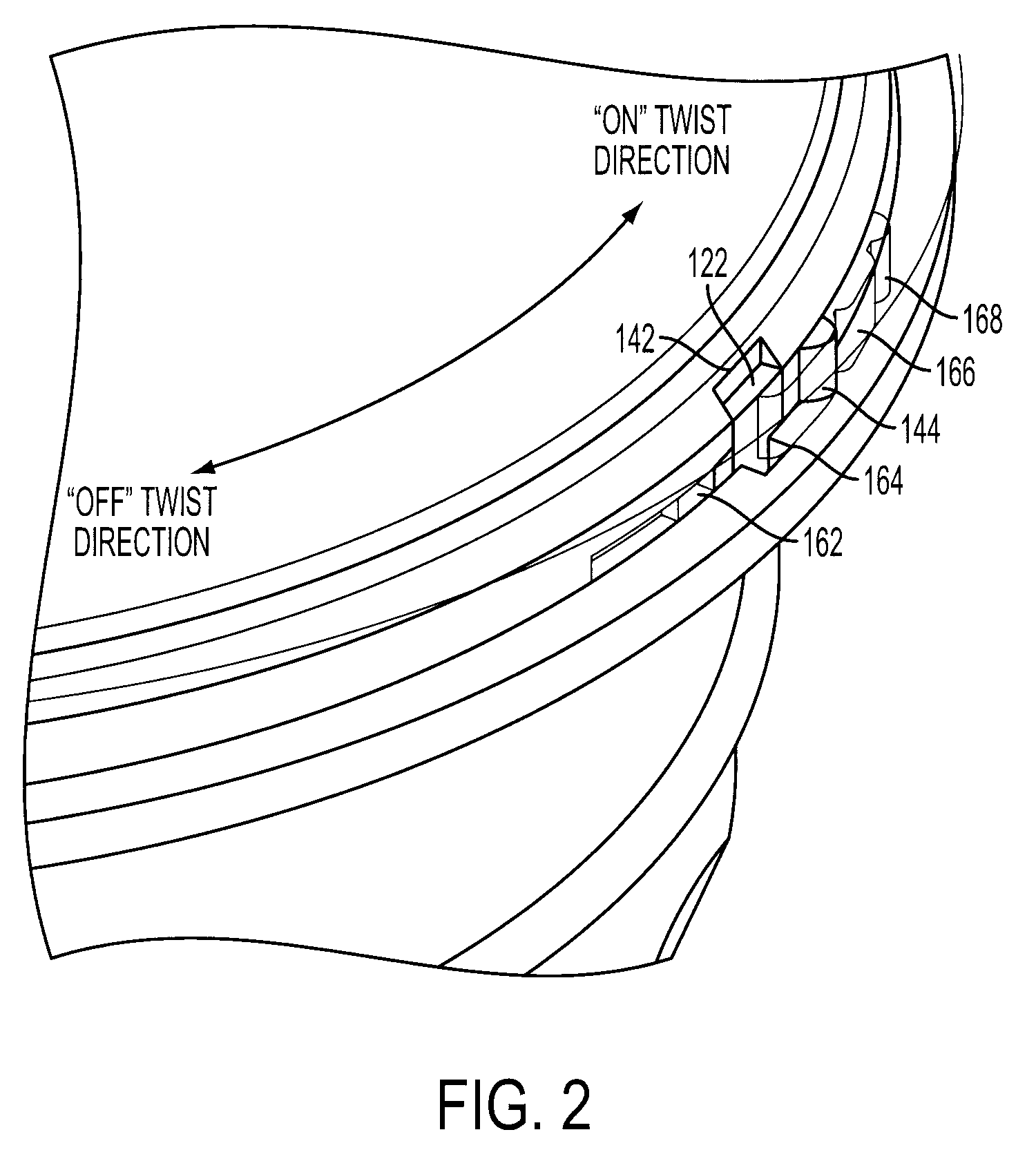
[0017]The invention provides an apparatus and method that uses a speaker grill surround ring to provide on / off and / or volume or other controls in products such as ultra portable speakers where conventional controls are undesirable or are aesthetically unacceptable.

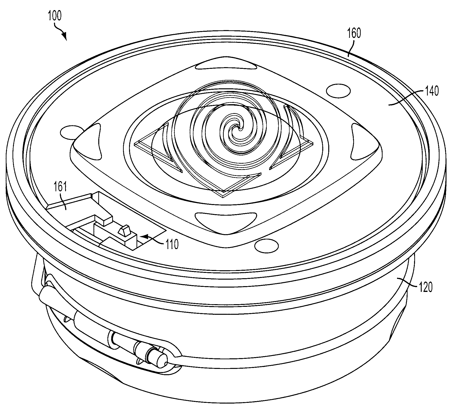
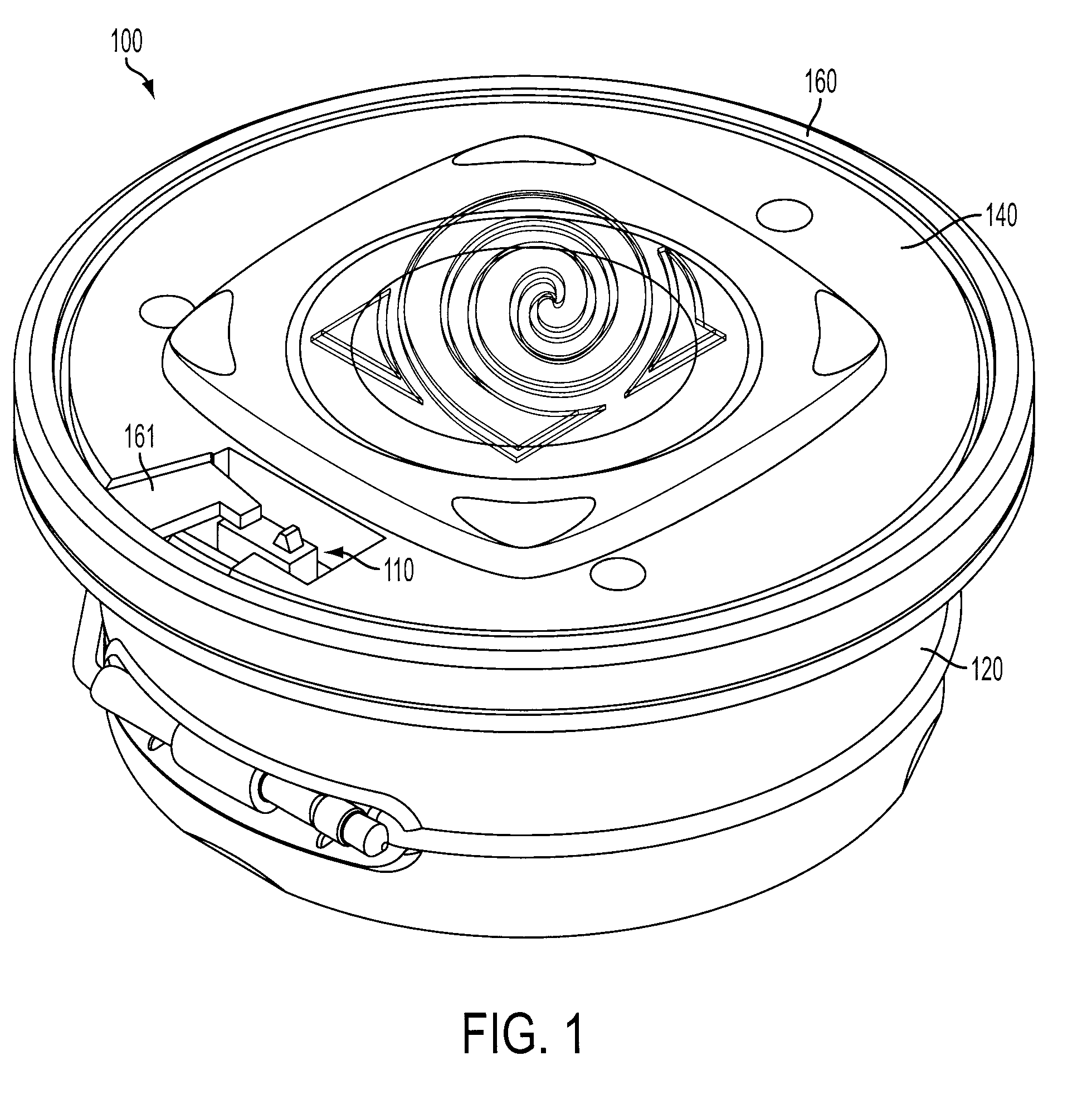
[0018]Referring first to FIG. 1, one embodiment, comprises a speaker 100 with a housing 120 a speaker baffle 140 and a twistable grill 160. The grill 160, is molded, with a separate edge ring that engages with and acts upon other parts of the speaker assembly. For example, the embodiment illustrated in FIG. 1, illustrates an implementation of an on / off switch implemented using a twistable edge ring 160 mounted on the speaker housing 120 which can be maintained in “on” and “off” positions. In the “on” position, a molded protrusion of the twistable ring 161 depresses...


PUM


Abstract

A twisting ring control for a compact speaker is rotatably mounted on a speaker encircling the speaker baffle. When the ring is rotated in one direction, the ring causes the speaker to be switched off, and when the ring is rotated in the opposite direction, the ring causes the speaker to be switched on. A volume control can be integrated into the same mechanism, and arranged such that, after the speaker is switched on, when the ring is rotated in one direction the volume is increased and when the ring is rotated in the opposite direction the volume is decreased.

Description


Claims


Application Information

Patent Timeline
Owner PLANTRONICS
Why Eureka
Try Eureka