

Ergonomic crutch
a crutch and ergonomic technology, applied in the field of medical devices, can solve problems such as no way
- Summary
- Abstract
- Description
- Claims
- Application Information
AI Technical Summary
Benefits of technology
Problems solved by technology
Method used
Image

Examples
first embodiment
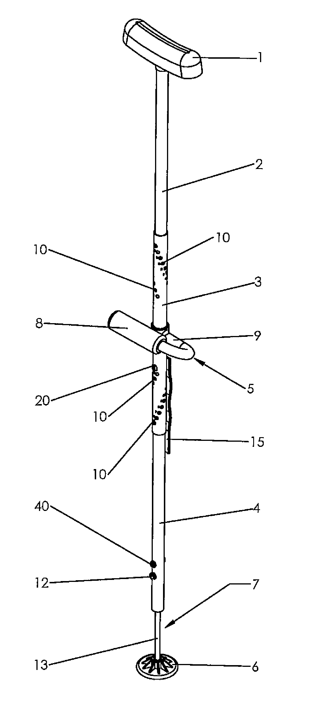
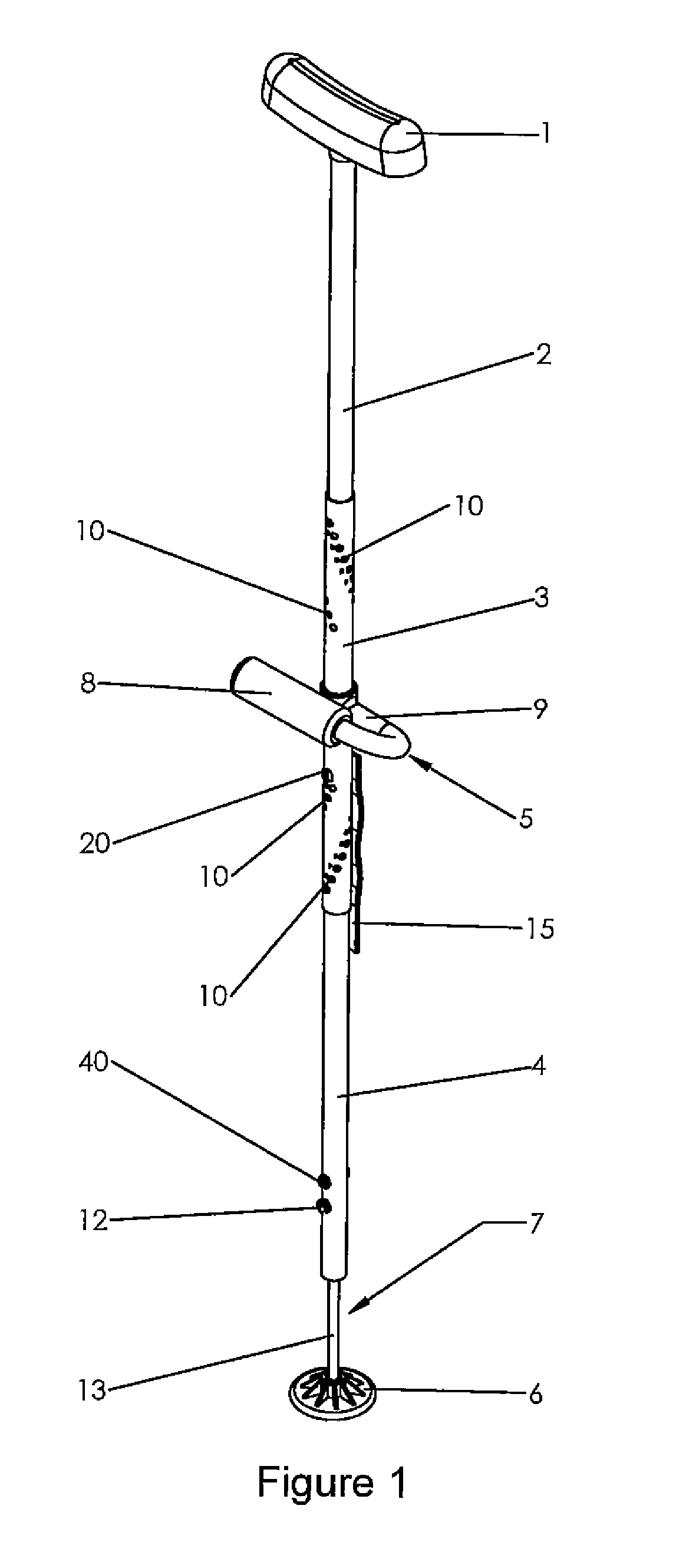
[0100]FIG. 1 is a perspective view of the present invention. As shown in this figure, the present invention is a crutch comprised of an armpit pad 1, a top tube 2, a middle tube 3, a bottom tube 4, a hand grip 5 and a foot pad 6. In this embodiment, the crutch further comprises a shock absorber 7. The armpit pad 1 is preferably gel-filled and ergonomically shaped so as to keep pressure off of the sensitive nerve areas of the armpit. As shown in subsequent figures, the armpit pad 1 both tilts vertically and swivels horizontally.
[0101]The hand grip 5 is welded onto the middle tube 3 and preferably comprises a gel-filled cushioned pad 8 for ease of grip. The present invention is not limited to any particular type of cushioned pad; the cushioned pad could be made of rubber or foam, for example. The hand grip 5 further comprises a metal bar 9 that extends in one direction from the middle tube 3, makes a U turn, and then extends in an opposite direction to a point beyond the middle tube 3...
second embodiment
[0126]FIG. 16 is a perspective view of the present invention. This embodiment is identical to the first embodiment except that the crutch does not include a shock absorber (and, for that reason, the bottom tube 4 may be longer than it was in the first embodiment). This embodiment would provide a horizontally swiveling and vertically tilting armpit pad 1, but it would not eliminate the problem (described above) of the armpit pad 1 traveling in an arc-shaped path as opposed to a horizontal line when the crutch is in use. It may, however, be less expensive to manufacture than the first embodiment.
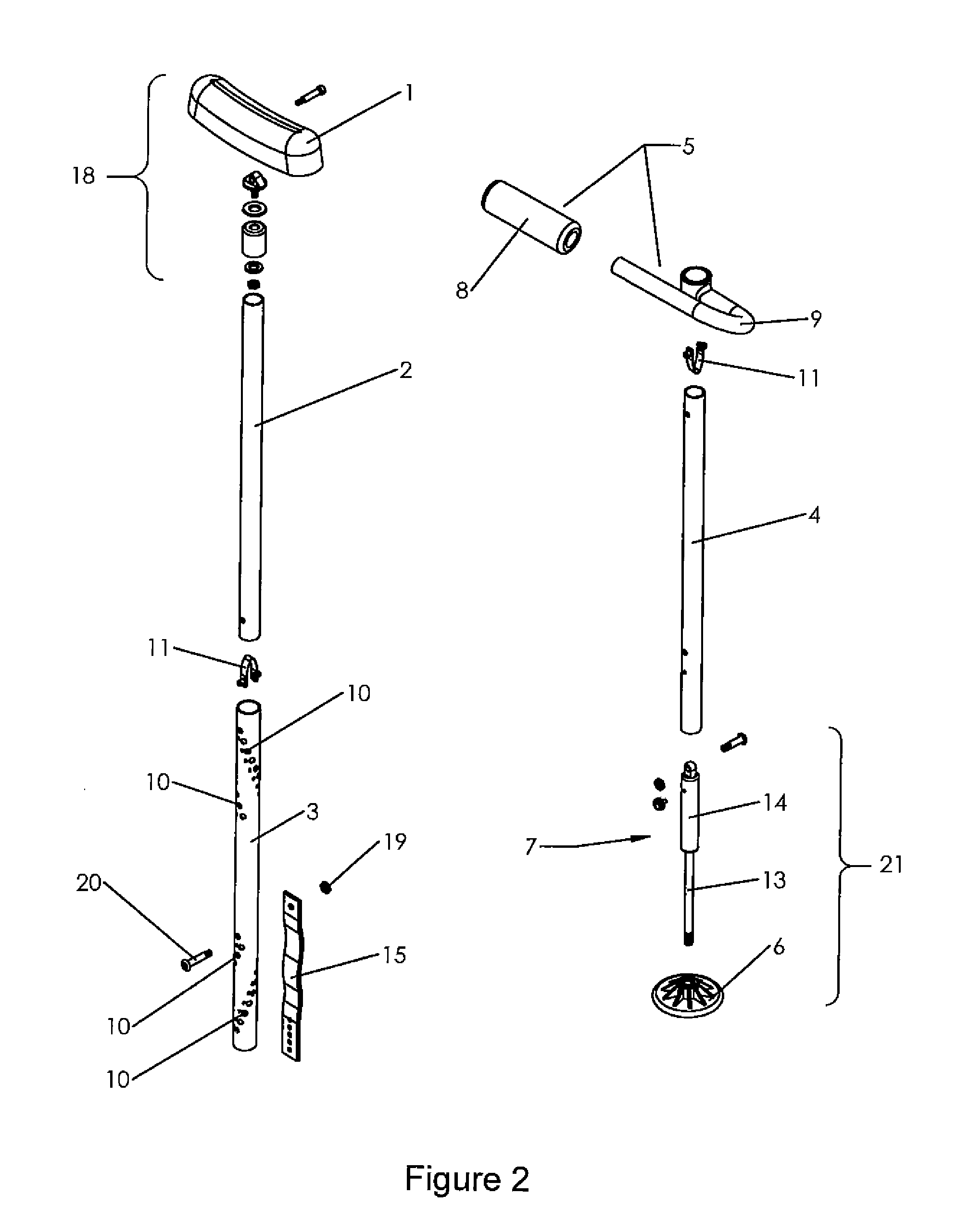
[0127]FIG. 17 is an exploded view of a second embodiment of the present invention. This embodiment is identical to the first embodiment except for the foot pad assembly 21 (compare to FIG. 2). In this embodiment, because there is no shock absorber, the bottom tube 4 is longer than it is in the first embodiment (alternately, if the bottom tube is not longer, the end piece 45 would have to be lo...
PUM
 Abstract
Description
Claims
Application Information