LED lamp having a convenient replacement structure

a technology of led modules and replacement structures, which is applied in the field of led lamps, can solve the problems of cumbersome disassembly and assembly of damaged led modules, and the difficulty of disassembling work, and achieves the effects of large luminous flux, and convenient replacement of led modules

Inactive Publication Date: 2009-10-15
FU ZHUN PRECISION IND SHENZHEN +1
View PDF6 Cites 33 Cited by
  • Summary
  • Abstract
  • Description
  • Claims
  • Application Information

AI Technical Summary

Benefits of technology

[0007]An LED lamp for providing a relatively large luminous flux, includes a housing and a pair of LED units mounted in the housing. The two LED units are separated from each other by a clapboard set in the housing. Each LED unit includes a plate, a plurality of LED modules disposed on the plate and a cover mounted to the plate to cover the LED modules. The cover forms a plurality of vents to expose LEDs of the LED modules therein. A plurality of first screws extends through the LED modules and the plate to secure them together, while a plurality of second screws extends through the plate, the cover and the housing to secure the whole LED unit to the housing. By providing the plate which serves as an interconnector between the LED modules and the housing, the LED modules can be simultaneously detached from the housing just by disassembling the plate from the housing. Thus, the replacement of the LED modules is quite easy and convenient.

Problems solved by technology

However, since each LED module is individually installed on a corresponding part of the housing by screws, if a certain number of the LED modules in the housing are damaged and need to be replaced, it is cumbersome to disassemble the damaged LED modules from the housing one by one.
In worse cases, when the number of the damaged LED modules is large, the dissembling work becomes more difficult and would spend so many times, which is extremely undesirable if the LED lamp is particularly in the case of some emergent lighting applications where an immediate replacement is imperative.

Method used


Image

  • LED lamp having a convenient replacement structure
  • LED lamp having a convenient replacement structure
  • LED lamp having a convenient replacement structure

Examples


Embodiment Construction

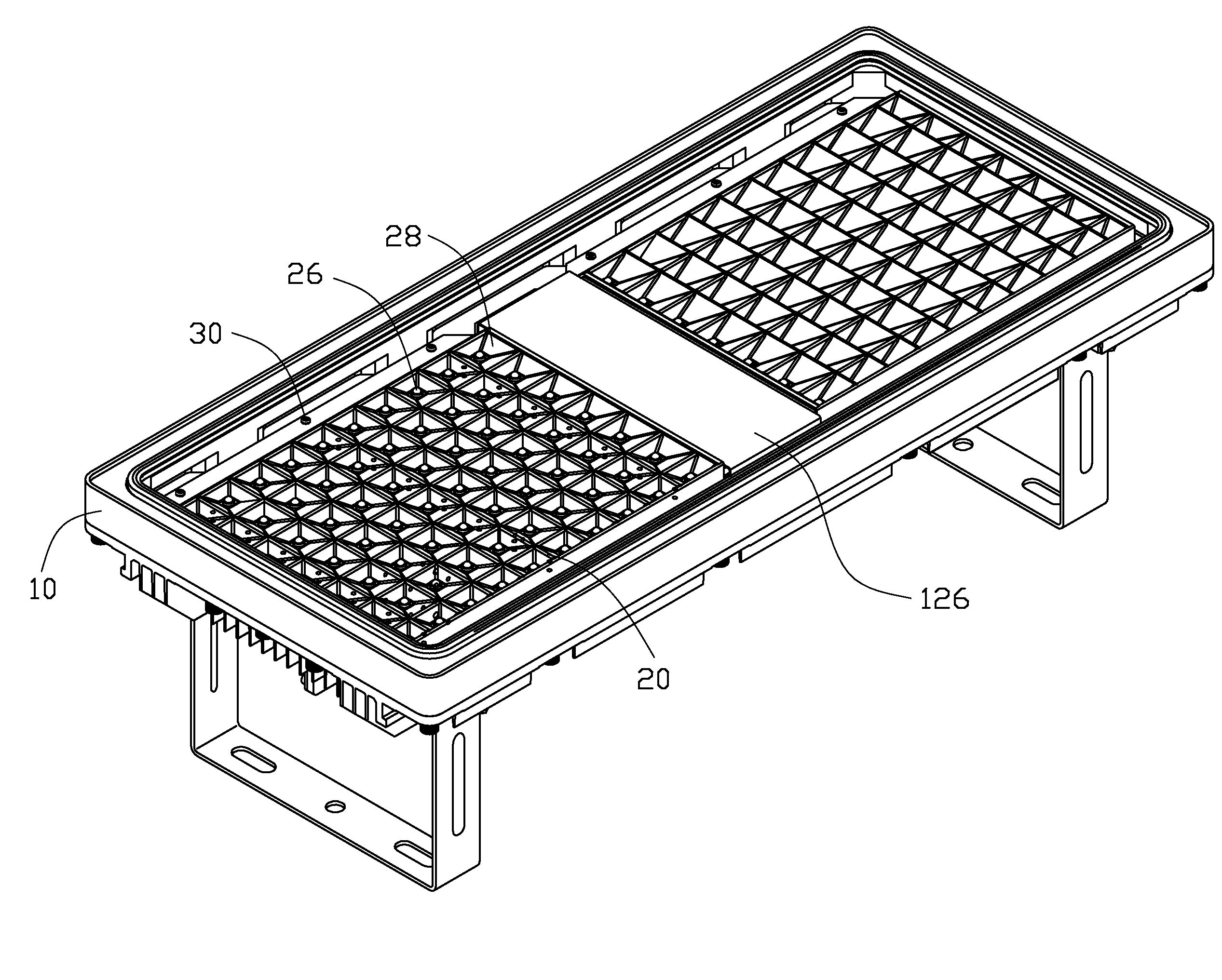
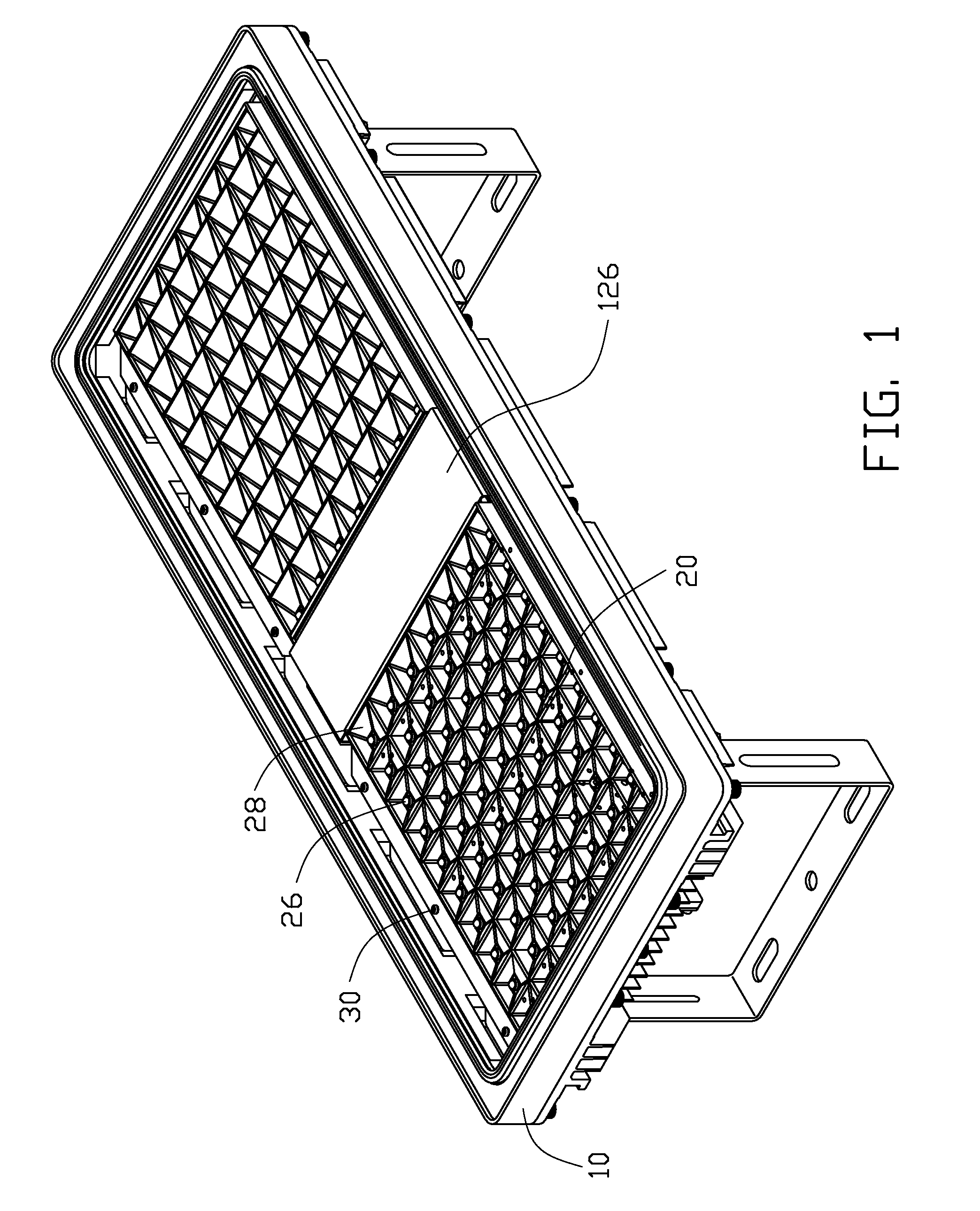
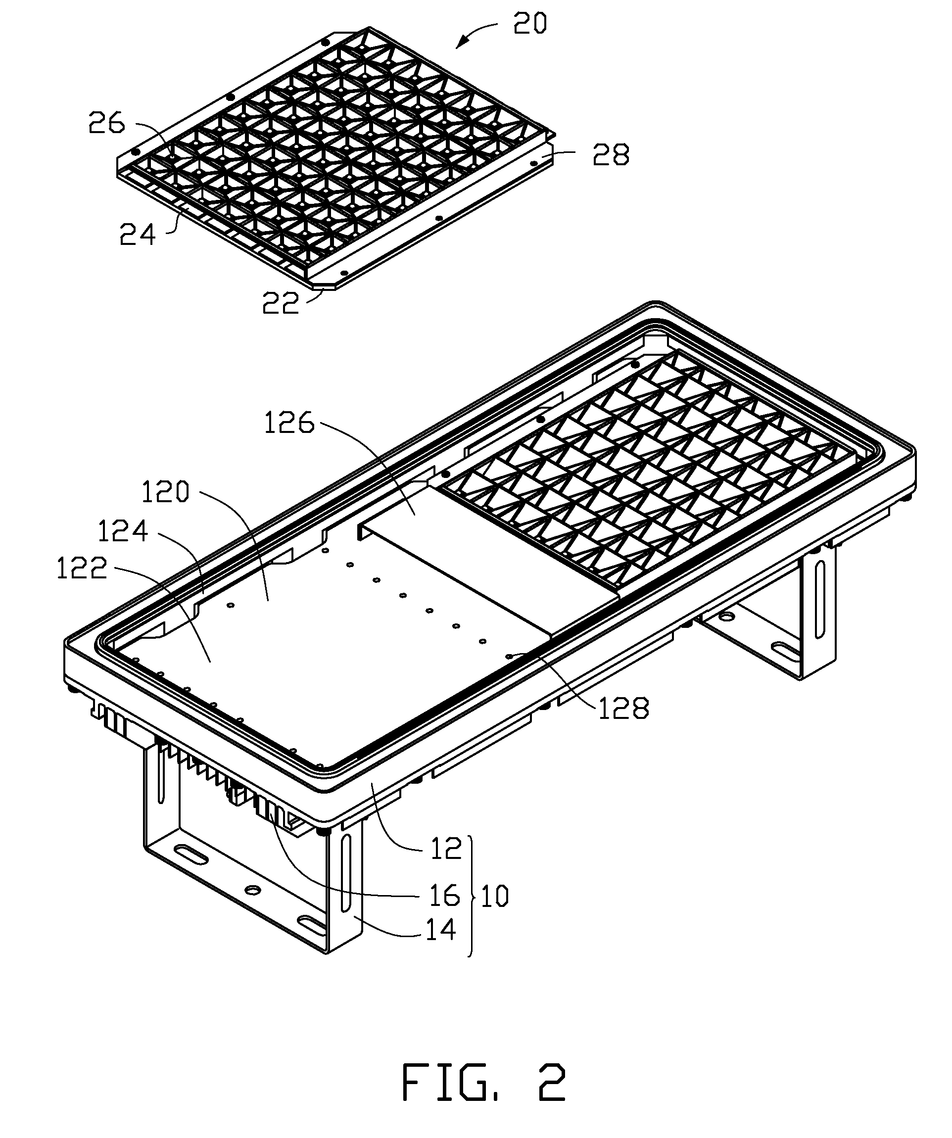
[0014]Referring to FIG. 1, an LED lamp in accordance with a preferred embodiment of the present invention is for being employed in some illuminating devices needing high luminous flux, such as a street lamp or a tunnel lamp. The LED lamp comprises a rectangular housing 10 and a pair of LED units 20 mounted in the housing 10 for emitting light out of the housing 10.

[0015]Also shown in FIGS. 2-3, the housing 10 includes a hollow casing 12, a plurality of fins 16 extending downwardly from a bottom face of the casing 12 for dissipating heat from the LED units 20, and a pair of U-shaped arms 14 pivotably attached to the casing 12 near two opposite ends of the casing 12. The casing 12 has an inner top face 122 which is planar, and an inner circumferential face 124 surrounding the top face 122. The inner top face 122 and the inner circumferential face 124 together enclose a rectangular room 120 in the housing 10 for receiving the LED units 20. An inverted U-shaped clapboard 126 is mounted ...


PUM


Abstract

An LED lamp for providing a relatively large luminous flux, includes a housing and a pair of LED units mounted in the housing. The two LED units are separated from each other by a clapboard set in the housing. Each LED unit includes a plate, a plurality of LED modules disposed on the plate and a cover laying on the plate and cover the LED modules. The cover forms a plurality of vents to expose LEDs of the LED modules therein. A plurality of first screws extends through the LED modules and the plate to secure them together, while a plurality of second screws extends through the plate, the cover and the housing to fix the whole LED unit to the housing. Each LED module has a printed circuit board and a plurality of LEDs on the printed circuit board.

Description

BACKGROUND OF THE INVENTION[0001]1. Field of the Invention[0002]The present invention relates to an LED lamp, and more particularly to an LED lamp incorporating a plurality of LED units which can be conveniently replaced.[0003]2. Description of Related Art[0004]LEDs have been available since the early 1960's. Because of the relatively high light-emitting efficiency of LEDs, nowadays LED usage has been increased in popularity in a variety of applications, e. g., residential, traffic, commercial, industrial settings. Conventionally, an LED lamp comprises a housing and a plurality of LED modules mutually independently mounted in the housing via multiple screws. The housing severs as a support for fixing the LED modules thereto, as well as a heat sink for dissipating heat generated by the LED modules to an ambient atmosphere.[0005]However, since each LED module is individually installed on a corresponding part of the housing by screws, if a certain number of the LED modules in the housi...

Claims


Application Information

Patent Timeline
Patent Type & Authority Applications(United States)
IPC IPC(8): F21V21/00F21V1/00F21S4/00
CPCF21V19/001F21V19/045F21V7/0083F21Y2105/001F21Y2101/02F21Y2105/10F21Y2115/10F21Y2113/00F21V19/04F21K9/20
Inventor HUANG, XING-GUIHE, LI
Owner FU ZHUN PRECISION IND SHENZHEN
Why Eureka
Try Eureka