Ventilating kitchen range subframe

Active Publication Date: 2009-10-22
ELECTROLUX HOME PROD CORP NV
View PDF45 Cites 11 Cited by
  • Summary
  • Abstract
  • Description
  • Claims
  • Application Information

AI Technical Summary

Benefits of technology

[0004]The present invention provides a device for improving the ventilation of a cooktop, while also providing improved mounting for various oven range components. In one aspect, the invention provides a kitchen range subframe that includes one or more air channels for passively directing air to and/or from an element enclosure within the kitchen range and a range component shelf for mounting one or more range components to the kitchen range subframe. The range components may include range control devices, which may further include an electronic control panel, such as a liquid crystal display. The range control devices may also include heating element controls.
[0005]In one embodiment, the air is directed to at least one side of the element enclosure, while in another embodiment the air is directed to both sides of the element enclosure. In further embodiments, the air channels have a U-shaped cross-section. In embodiments with U-shaped air channels, air may be directed to the element enclosure through one or more airflow cutouts within an inside channel wall of the air channels.
[0006]In another aspect, the present invention provides a ventilated kitchen range that includes an element enclosure; one or more heating elements within the element enclosure; a kitchen range subframe positioned in front of the element enclosure, wherein the kitchen range subframe comprises a range component shelf and at least one air channel positioned along a side of the element enclosure for passively directing a

Problems solved by technology

Ventilation holes in the cooktop can be used to help improve ventilation, but these ventilation holes may be unsightly and provide the opportunity for spillage to enter the burner box.

Method used


Image

  • Ventilating kitchen range subframe
  • Ventilating kitchen range subframe
  • Ventilating kitchen range subframe

Examples


Embodiment Construction

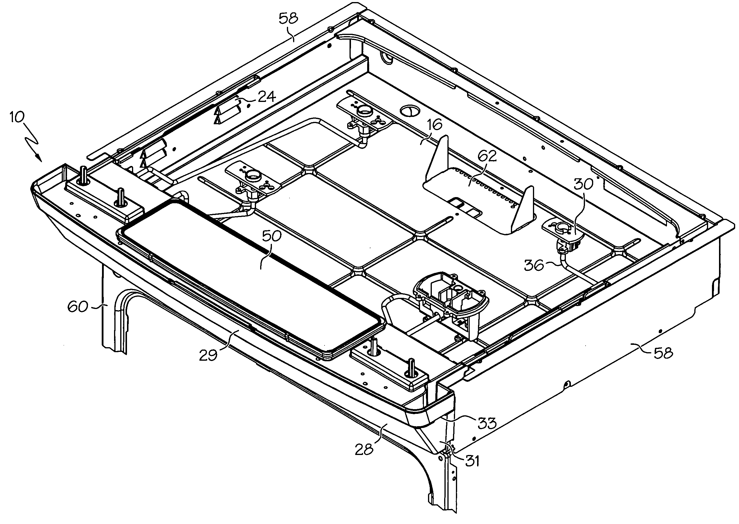
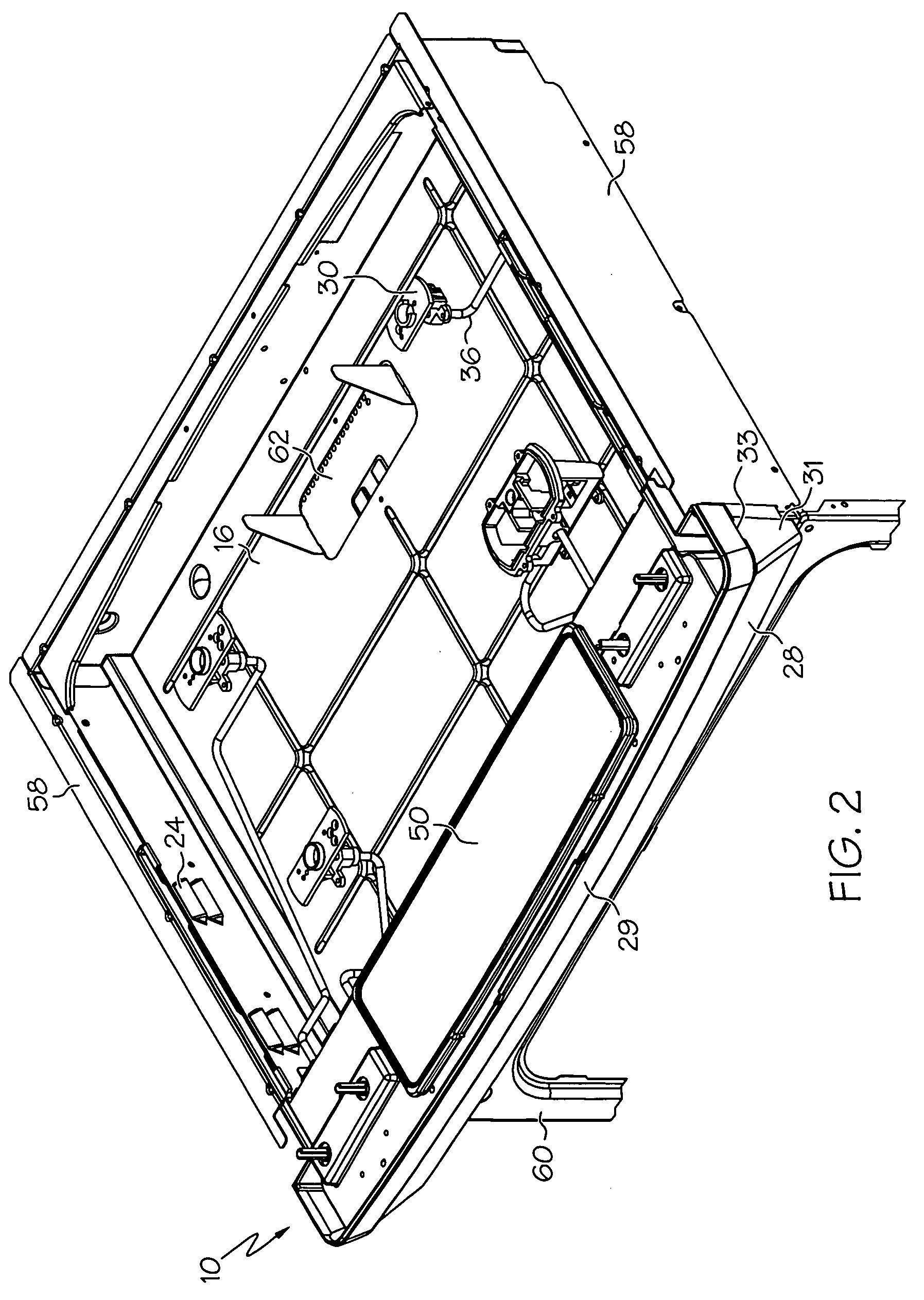
[0016]The present invention provides a kitchen range subframe that fits to a kitchen range. A kitchen range subframe, as defined herein, is a component that provides a separate structure within a kitchen range to carry other range components. The subframe includes air channels for passively directing air to an element enclosure within the kitchen range and a range component shelf for mounting one or more range components to the kitchen range subframe.

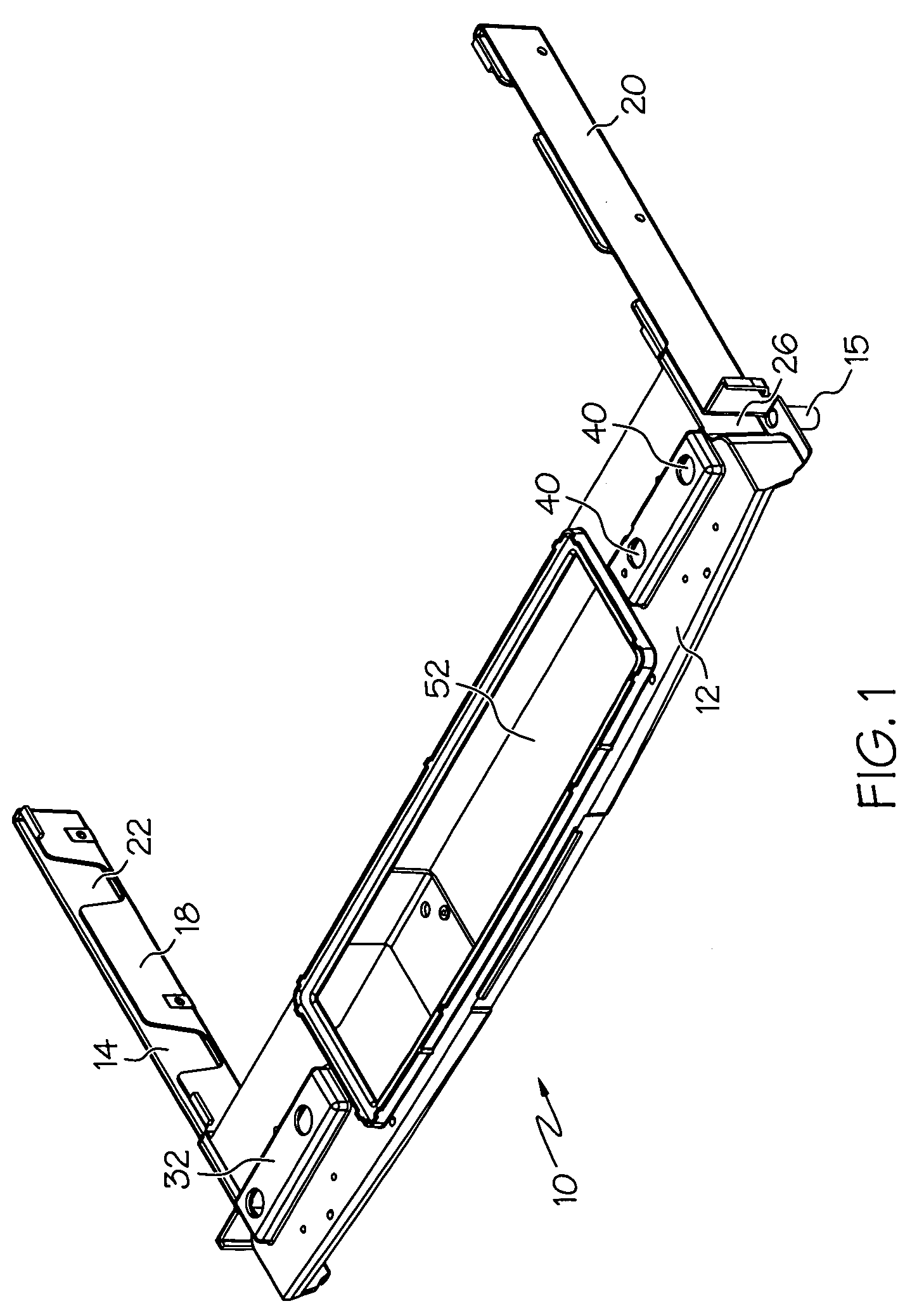
[0017]An embodiment of the kitchen range subframe is shown in FIG. 1. As shown in the figure, the kitchen range subframe 10 includes a range component shelf 12. The range component shelf 12 provides a surface that is configured to hold one or more range components, such as range control devices. The kitchen range subframe 10 also includes one or more air channels 14 for directing air to the element enclosure within the kitchen range. These air channels 14 can have various configurations, but should be able to direct air flowing from out...


PUM


Abstract

A kitchen range subframe includes air channels for passively directing air to and / or from an element enclosure within the kitchen range, and a range component shelf that is configured to mount one or more range components to the kitchen range subframe. The kitchen range subframe provides improved ventilation for the kitchen range, and mounting locations for range components such as gas lines and kitchen range controls.

Description

FIELD OF THE INVENTION[0001]The present invention relates to kitchen ranges and, in particular, to a kitchen range subframe that provides ventilation for the kitchen range element enclosure and support for one or more range components.BACKGROUND[0002]Kitchen ranges are typically ventilated to improve their performance. Ranges with electrical burners are typically ventilated using airflow systems to cool the range controls and the electric heating elements, and minimize the formation of hot spots on the cooktop surface. For example, U.S. Pat. No. 4,551,600 describes a mechanism for cooling the interior of an induction heating kitchen range by using a fan to drive air through various chambers underneath the cooktop and then out through ventilation holes in the cooktop. U.S. Pat. No. 6,444,958 describes another arrangement for ventilating a kitchen range in which air is drawn into the burner box by a fan and past electronic controls in another compartment in order to cool these control...

Claims


Application Information

Patent Timeline
IPC IPC(8): F24C15/20F24C3/00F24F7/00
CPCF24C15/10F24C3/124
Inventor BRANT, RONALD G.CLARK, ADAMMARLER, JAMES
Owner ELECTROLUX HOME PROD CORP NV
Why Eureka
Try Eureka