Clamping device

a technology of clamping device and clamping plate, which is applied in the direction of metal-working holder, positioning apparatus, support, etc., can solve the problems of tool acquisition and maintenance cost, tendency of bulging between work pieces, and more pronounced problems

Inactive Publication Date: 2009-10-22
QUICKMILL
View PDF13 Cites 19 Cited by
  • Summary
  • Abstract
  • Description
  • Claims
  • Application Information

AI Technical Summary

Problems solved by technology

These tools are expensive to acquire and maintain.
As the process proceeds, there is a tendency of bulging between the work pieces as material shavings force themselves in between the work pieces.
This problem is more pronounced as the size of the work pieces increase, the amount of machining that is done on the work pieces and as the distance from the clamped peripheral edges increases.
For example, the problem may be come acute when the machining step occurs in a central region of these work pieces.

Method used


Image

  • Clamping device
  • Clamping device
  • Clamping device

Examples


Embodiment Construction

[0018]It should be understood that the invention is not limited in its application to the details of construction and the arrangement of components set forth in the following description or illustrated in the drawings. The invention is capable of other embodiments and of being practiced or of being carried out in various ways. Also, it is to be understood that the phraseology and terminology used herein is for the purpose of description and should not be regarded as limiting. The use of “including,”“comprising,” or “having” and variations thereof herein is meant to encompass the items listed thereafter and equivalents thereof as well as additional items. Unless limited otherwise, the terms “connected,”“coupled,” and “mounted,” and variations thereof herein are used broadly and encompass direct and indirect connections, couplings, and mountings. In addition, the terms “connected” and “coupled” and variations thereof are not restricted to physical or mechanical connections or coupling...


PUM

PropertyMeasurementUnit
angle of inclination thetaaaaaaaaaaa
clamping forceaaaaaaaaaa
reaction surfaceaaaaaaaaaa

Abstract

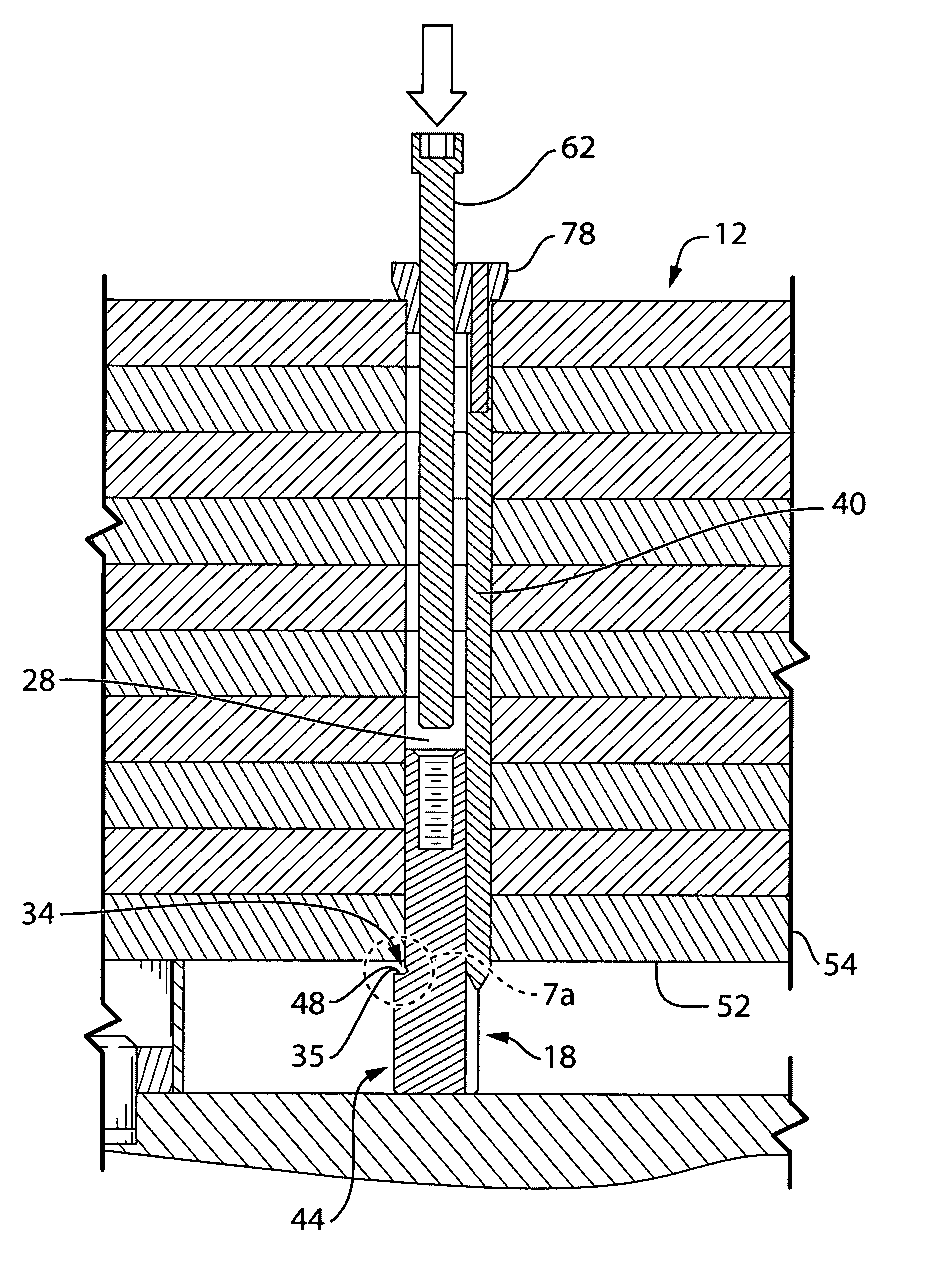
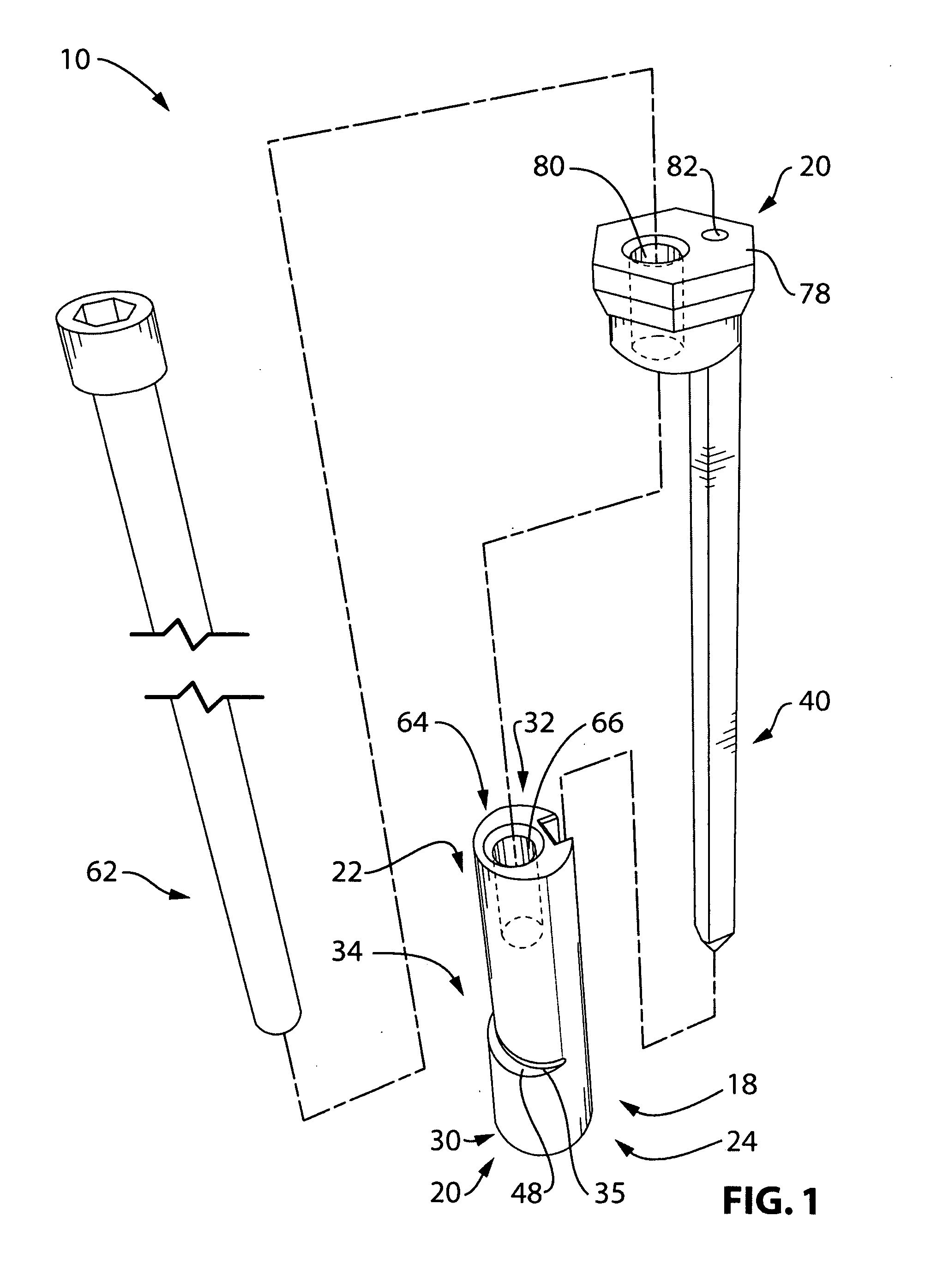
Disclosed herein is a securing device for plate-like work pieces, comprising a body member and an anchor member, the body member having a first end and a second end, the first end having an engagement portion, a biasing member to basis the body member laterally within a plurality of aligned openings in said work pieces and biasing the engagement portion past the openings, the engagement portion having an operative surface to engage an outer surface on a first outer work piece, the body member including a threadable portion, the anchor member being operable to engage an outer surface on a second outer work piece, the anchor member including a threaded member to engage the threadable portion, the threaded member be rotationally operational to draw the body member toward the anchor member.

Description

REFERENCE TO COPENDING APPLICATIONS[0001]The entire subject matter of U.S. Provisional application 61 / 064,676 filed Mar. 19, 2008 and entitled CAMPING DEVICE is incorporated herein by reference. The applicant claims priority benefit under Title 35, United States Code, Section 119 of the above application.BACKGROUND OF THE INVENTION[0002]1. Field of the Invention[0003]This invention relates in general to devices and methods for securing groups of two or more work pieces during machining.[0004]2. Description of the Related Art[0005]The precision machining of large work pieces, such as plate-like work pieces, requires the use of a wide array of machine tools such as gauges, templates, cooling systems, hydraulic clamps, and drill-sets. These tools are expensive to acquire and maintain.[0006]Large work pieces, such as steel plates, are typically manufactured using a large gantry milling machine. In one conventional system, steel plates are stacked on a milling table and clamped at regula...

Claims


Application Information

Patent Timeline
Patent Type & Authority Applications(United States)
IPC IPC(8): B25B11/00B25B5/10B23Q3/00
CPCB23Q3/061B25B5/10B25B5/145Y10T29/49948B23Q2240/002Y10T29/4981B25B31/005
Inventor PIGGOTT, DAVID C.
Owner QUICKMILL
Why Eureka
Try Eureka