Electric power source system and method for the same

Inactive Publication Date: 2009-10-22
TOYOTA JIDOSHA KK
View PDF6 Cites 34 Cited by
  • Summary
  • Abstract
  • Description
  • Claims
  • Application Information

AI Technical Summary

Benefits of technology

[0007]The invention provides an electric power source system that prevents the momentary interruption in the supply of electric po

Problems solved by technology

In the foregoing related-art technology that enables the bidirectional exchange of current between different voltage systems, however, when the voltage converter switch

Method used


Image

  • Electric power source system and method for the same
  • Electric power source system and method for the same
  • Electric power source system and method for the same

Examples


first embodiment

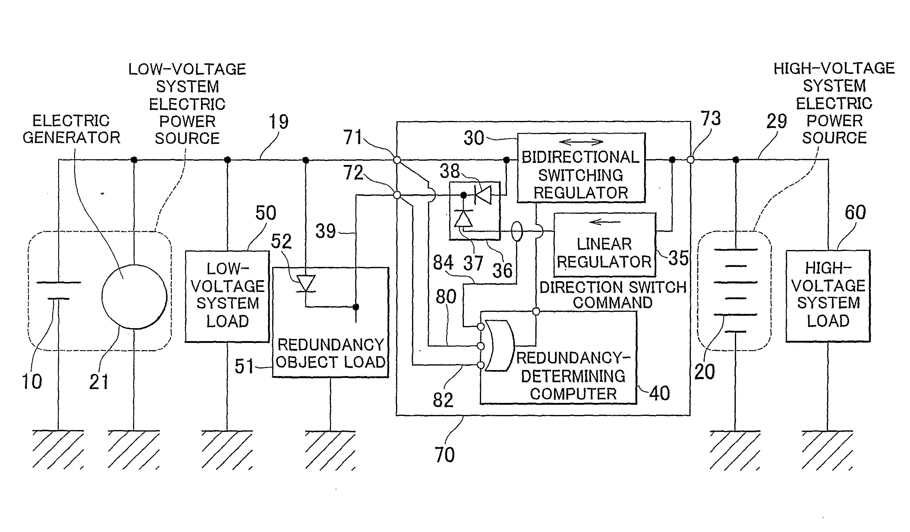
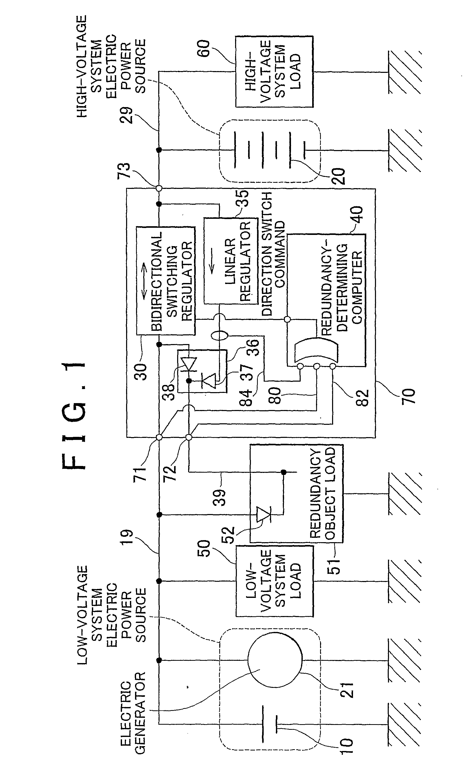
[0023]Hereinafter, example embodiments of the invention will be described with reference to the accompanying drawings. FIG. 1 is a schematic diagram showing the vehicular electric power source system of the invention. A vehicle in which a vehicular electric power source system is mounted is equipped with a high-voltage system battery 20 that is an electricity storage device of a high-voltage system (e.g., a 42-V system), a low-voltage system battery 10 that is an electricity storage device of a low-voltage system (e.g., a 14-V system), a DC / DC voltage converter (DC / DC converter) 70 that has at least a step-down voltage conversion mode, which decreases the voltage of the high-voltage system to the voltage of the low-voltage system and thus supplies electric power from the high-voltage system to the low-voltage system, and a step-up voltage conversion mode, which increases the voltage of the low-voltage system to the voltage of the high-voltage system and thus supplies electric power ...

second embodiment

[0065]Thus, the vehicular electric power source system of the second embodiment is constructed so that the direction of current that flows via the bidirectional switching regulator 30 switches from the step-down direction to the step-up direction after current flows in the step-up direction via the switching regulator 45. Therefore, it is possible to prevent the occurrence of a state where the electric power supply to the redundancy object load 51 momentarily declines or stops when the direction of the electric power transfer of the bidirectional switching regulator 30 is switched from the step-down direction to the step-up direction because of a decline of the electric power supply performance of the high-voltage system electric power source or the like. Furthermore, because the switching regulator 45 is provided, it is possible to cause current to flow in the step-up direction even if the redundancy object load 51 is connected to the high-voltage system.

[0066]While the example emb...


PUM


Abstract

An electric power source system in which a momentary interruption of the electric power supply does not occur when the direction of voltage conversion is switched by a voltage conversion device that is capable of bidirectional voltage conversion. The electric power source system includes a bidirectional switching regulator that selectively switches between the voltage conversion in the step-up direction from a low-voltage system to a high-voltage system and the voltage conversion in the step-down direction from the high-voltage system to the low-voltage system, and a linear regulator, connected in parallel to the bidirectional switching regulator, that converts voltage in the step-down direction. The direction of current that flows via the bidirectional switching regulator switches from the step-up direction to the step-down direction after current flows in the step-down direction via the linear regulator.

Description

BACKGROUND OF THE INVENTION[0001]1. Field of the Invention[0002]The invention relates to an electric power source system that has a plurality of electric power sources, and a method that controls an electric power source system.[0003]2. Description of the Related Art[0004]An electric power source control device that employs batteries of two different voltage systems is described in Japanese Patent Application Publication No. JP-A-2002-176704. In some cases, electric power source control devices that employ a plurality of electricity storage devices, including the electric power source control device described in JP-A-2002-176704, convert the voltage of a first electricity storage device to the voltage of a second electricity storage device via voltage converter, such as a DC / DC converter or the like and thereby charge the second electricity storage device or supply electric power to an electrical load whose direct power source is the second electricity storage device.[0005]In the fo...

Claims


Application Information

Patent Timeline
IPC IPC(8): G05F1/618B60L50/15
CPCH02J2001/008H02M2001/0045H02M3/1582B60R16/03H02J1/082H02J2310/46H02M1/0045
Inventor ITO, KOJIESAKA, TOSHINORIMATSUTO, HIDENORI
Owner TOYOTA JIDOSHA KK
Why Eureka
Try Eureka