Respiratory connector and arrangement for connecting an inspiratory tube and an expiratory tube to a medical apparatus

a technology for respiratory connectors and medical devices, which is applied in the direction of respiratory devices, medical devices, other medical devices, etc., can solve the problems of dangerous situations, complicated connections, and complicated and time-consuming

Inactive Publication Date: 2009-10-29
CAREFUSION
View PDF18 Cites 23 Cited by
  • Summary
  • Abstract
  • Description
  • Claims
  • Application Information

AI Technical Summary

Problems solved by technology

While using coaxial inspiration and expiration tubes a connector is usually more complicated than when using tubes, which are side by side.
This is too complicated and time consuming.
However, the adapter and the connector constitute a long device protruding from the side of the machine making it clumsy and vulnerable to users' pushes which may even cause a dangerous situation.
Also the more connections have to be made the more leaks and unintentional disconnections can appear.
Especially a leak between inspiratory and expiratory line may be hazardous to the patient, because the patient may re-breath carbon dioxide.
Further a disadvantage is that the user has to use both hands when connecting the connector at the machine end to the adapter, because the user has to hold in one of his / her hands the adapter and simultaneously in another hand the connector and to push the connector strongly towards the adapter to make both the inspiration and expiration channels' joints tight to avoid leakages.
From mechanical perspective, the manufacturing of a reliable connector with two coaxial conical surfaces is very challenging.
Especially with reusable parts the wearing of the sealing surfaces may cause these conical connectors not to be reliably sealing simultaneously.
Also the molding tools wear and may cause similar risks.
However, a leak between the inner and outer channel of coaxial tubing is much more difficult to detect, especially without separate patient gas monitoring.

Method used


Image

  • Respiratory connector and arrangement for connecting an inspiratory tube and an expiratory tube to a medical apparatus
  • Respiratory connector and arrangement for connecting an inspiratory tube and an expiratory tube to a medical apparatus
  • Respiratory connector and arrangement for connecting an inspiratory tube and an expiratory tube to a medical apparatus

Examples


Embodiment Construction

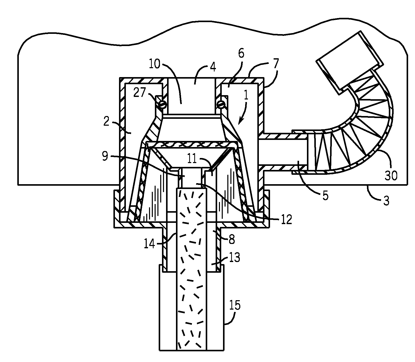
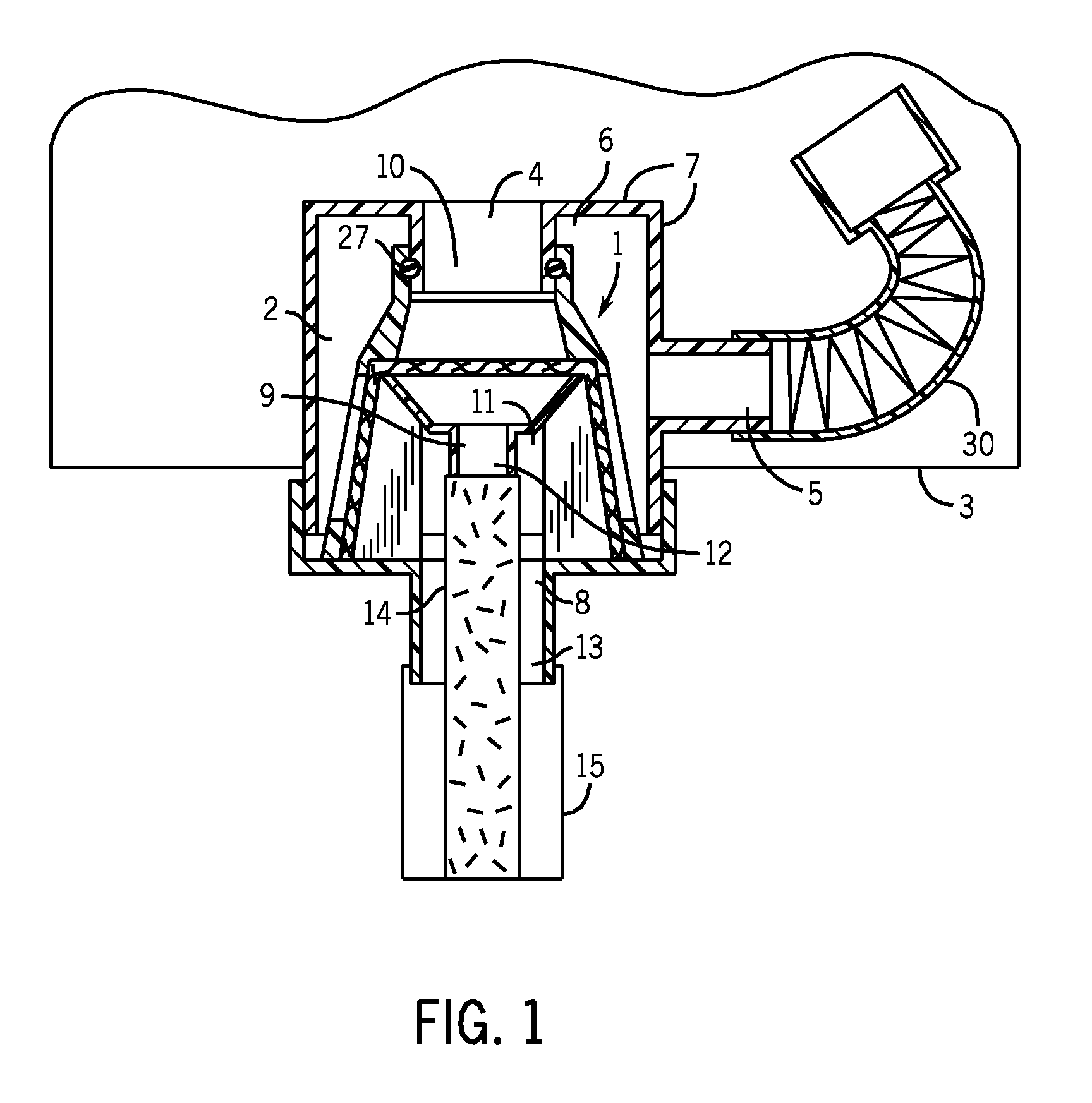
[0018]FIG. 1 shows a respiratory connector 1 connected to a coupling point 2 included in a medical apparatus 3 such as an anesthesia machine or a ventilator. The coupling point 2 is inside the medical apparatus 3 in FIG. 1, but as well it can be outside the medical apparatus 3, too. Further the coupling point 2 can be an integral part of the medical apparatus 3 especially if the coupling point 2 is inside the medical apparatus 3 or detachable especially in case the coupling point 2 is outside the medical apparatus 3. The coupling point 2 comprises two ports, one of which ports is an inspiratory port 4 and another is an expiratory port 5. The inspiratory port 4 is for guiding an inspiratory flow from the medical apparatus 3 towards the respiratory connector 1 and further to a patient (not shown). The expiratory port 5 is for guiding an expiratory flow coming from the patient through the respiratory connector 1 to the medical apparatus 3. The coupling point 2 includes a hollow 6 surro...


PUM


Abstract

A respiratory connector for connecting an inspiratory tube and an expiratory tube to a coupling point of a medical apparatus is disclosed here. The respiratory connector includes a base element and two channels inside the base element, one of the channels is for an inspiratory flow and another is for an expiratory flow. The respiratory connector also includes a first sealable zone for sealing the base element with the coupling point and a second sealable zone at a distance from the first sealable zone for sealing with the coupling point. Both channels at least partly extend inside the base element between the first sealable zone and the second sealable zone. An arrangement for connecting an inspiratory tube and an expiratory tube to a medical apparatus is also disclosed.

Description

BACKGROUND OF THE INVENTION[0001]This disclosure relates generally to a respiratory connector and an arrangement for connecting an inspiratory tube and an expiratory tube to a medical apparatus.[0002]Conventional anesthesia machines and critical care ventilators are connected to a patient by means of inspiratory and expiratory tubes, which tubes can be side by side or as today more often coaxial. The reason to use coaxial tubes is that in that case expiration gas warms inspiration gas making breathing more pleasant for the patient. Usually an expiration air is flowing along an outer tube from the patient towards the machine and an inspiration air is flowing along an inner tube from the machine to the patient, whereby a warming of the inspiration air can be maximized and avoid cooling due to a lower room temperature. At machine end inspiratory and expiratory tubes need to be connected by a hospital personnel to the anesthesia machine or the ventilator preventing expiration and inspir...

Claims


Application Information

Patent Timeline
Patent Type & Authority Applications(United States)
IPC IPC(8): A61M16/08
CPCA61M16/0816A61M16/1055A61M2016/0027A61M16/107A61M2230/60A61M16/0858A61M16/1065A61M2230/10A61M16/0841
Inventor VARIS, ANURANTA, JANNE
Owner CAREFUSION
Why Eureka
Try Eureka