Aspiration flow resistor

a technology of resistor and aspiration flow, which is applied in the field of aspiration flow resistor, ophthalmic surgery, can solve the problems of increasing the chance of aspirant clogging within the coil, the need for rapid response time, and the increase of the potential for serious problems

Inactive Publication Date: 2007-05-15
BAUSCH & LOMB INC
View PDF11 Cites 8 Cited by
  • Summary
  • Abstract
  • Description
  • Claims
  • Application Information

AI Technical Summary

Problems solved by technology

However, these higher vacuum levels result in the need for rapid response times by the surgeon when events, such as occlusion occur in the aspiration line.
The higher the vacuum levels, the quicker events occur and thus the potential for serious problems increases, such as the potential for tearing of the capsular bag.
However, a downside to the coiled tubing is that the chances of aspirant clogging within the coils is increased due to the elliptical cross-section and bent kinks that may occur in the tubing.
The filter may still clog however.

Method used


Image

  • Aspiration flow resistor
  • Aspiration flow resistor

Examples


Embodiment Construction

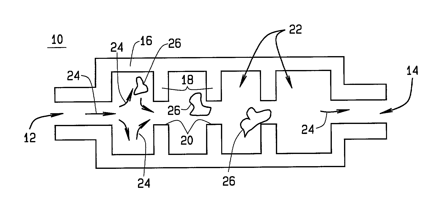
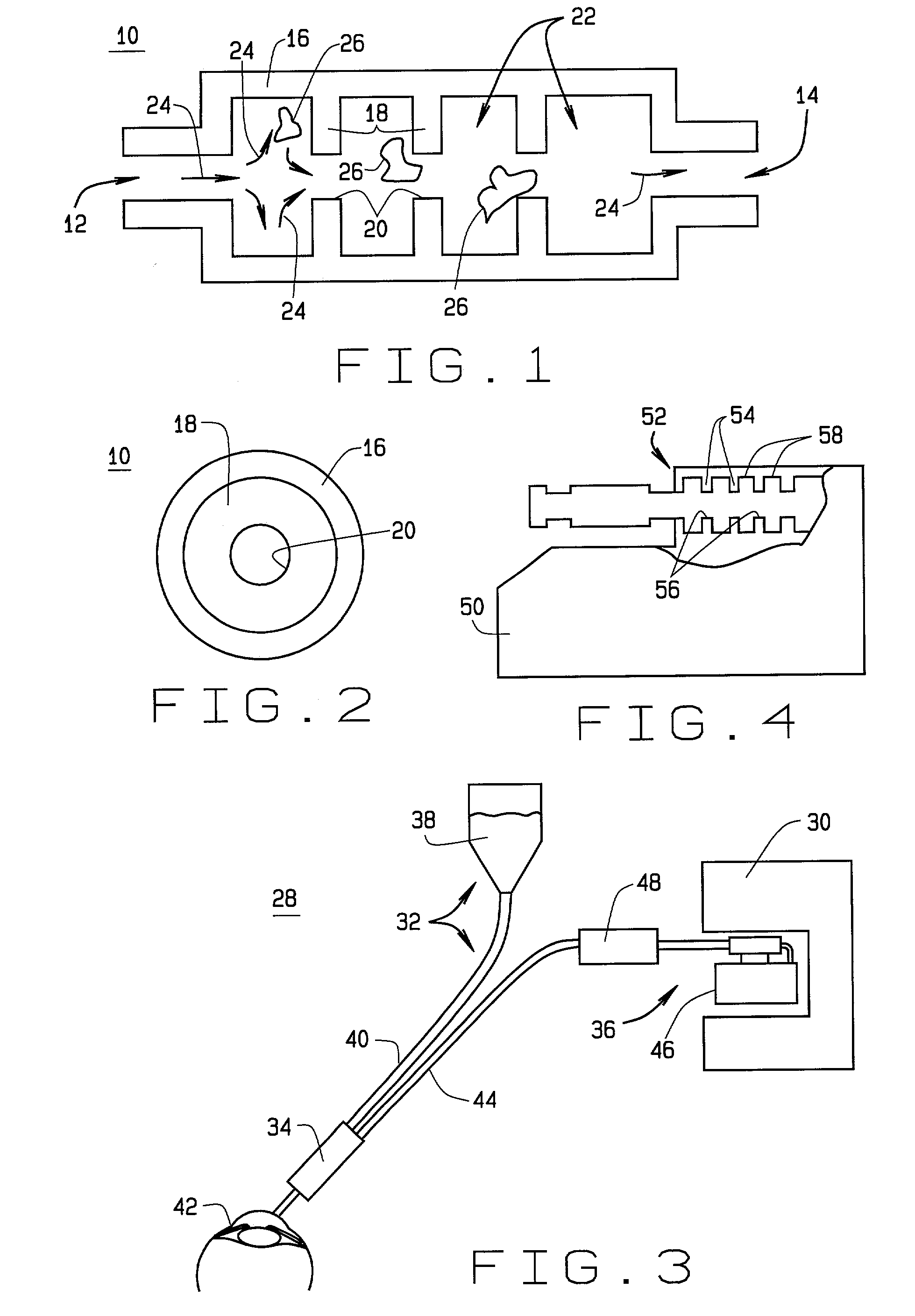
[0012]FIG. 1 shows an aspirant flow resistor 10 in accordance with the present invention. Resistor 10 includes an inlet 12 and an outlet 14. A housing 16 is connected to the inlet 12 and the outlet 14, a series of spaced walls 18 are disposed between the inlet 12 and the outlet 14, wherein each wall 18 has at least one orifice 20 for allowing aspirant to flow through the walls 18 and from the inlet to the outlet. Preferably resistor 10 may be formed of metal, plastic, or other suitable material for ophthalmic surgery.

[0013]The walls 18 and the inlet 12 and the outlet 14 together with the housing 16 define a plurality of aspiration flow chambers 22 such that as aspirant flows from the inlet 12 to the outlet 14 a pressure decrease in the aspirant flow occurs at each wall 18 and therein resistor 10 provides resistance to aspirant flow. Aspirant flow is shown by arrows 24 and at each wall 18 and specifically at the orifice 20 a pressure increase in the aspirant flow is experienced.

[0014...


PUM


Abstract

An aspiration flow resistor 10 includes an inlet 12 and an outlet 14. A housing 16 is connected to the inlet 12 and outlet 14. A series of spaced walls 18 are disposed between the inlet 12 and the outlet 14. The walls 18 and the inlet 12 and the outlet 14 together with the housing 16 define a plurality of aspiration flow chambers 22. As aspirant flows from the inlet 12 to the outlet 14, a pressure decrease in the aspirant flow occurs at each wall 18 to provide resistance to aspirant flow.

Description

BACKGROUND OF THE INVENTION[0001]1. Field of the Invention[0002]The present invention is related to devices for restricting the flow of aspirant during surgery, especially ophthalmic surgery. In particular, the present invention relates to devices that form a plurality of aspiration flow chambers for causing a pressure decrease of aspirant flow at each chamber for increasing a resistance of aspirant flow.[0003]2. Description of Related Art[0004]During eye surgery, especially cataract surgery, surgeons experience a tension between the amount of vacuum or aspiration to be used on a patient's eye and the time period in which the surgeon has to respond to events that may occur during surgery. Surgeons typically prefer high-vacuum levels to provide a higher holding force for the cataract. However, these higher vacuum levels result in the need for rapid response times by the surgeon when events, such as occlusion occur in the aspiration line. The higher the vacuum levels, the quicker even...

Claims


Application Information

Patent Timeline
Patent Type & Authority Patents(United States)
IPC IPC(8): A61M1/00A61F9/007
CPCA61M1/0031A61F9/007A61M1/0001A61M1/0058A61M2210/0612A61M1/74A61M1/60A61M1/77A61M2206/14A61M2205/3334A61M1/72
Inventor CULL, LAURENCE J.PERKINS, JAMES T.FITZGERALD, MATTHEW J.
Owner BAUSCH & LOMB INC
Why Eureka
Try Eureka