
Pulsation pressure decreased type pump for vehicle slip control system

a technology of a control system and a pump, which is applied in the direction of pulse equalisation, pump components, positive displacement liquid engines, etc., can solve the problem of vehicle occasionally slipping

Inactive Publication Date: 2008-12-25
HYUNDAI MOBIS CO LTD
View PDF10 Cites 22 Cited by
  • Summary
  • Abstract
  • Description
  • Claims
  • Application Information

AI Technical Summary

Benefits of technology

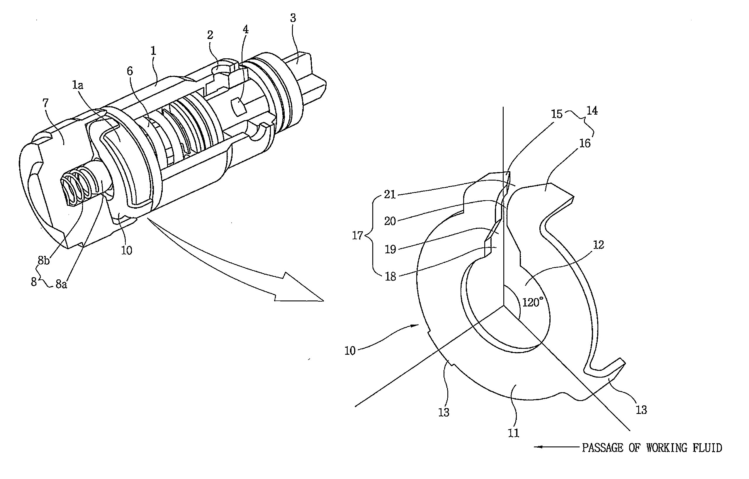
[0007]Embodiments of the present invention help overcome the drawbacks of the brake system and provide a pulsation pressure decreased type pump for a vehicle slip control system that includes an orifice provided on a discharge channel of a pump that discharges a working fluid using a piston reciprocated by a cam during operation. When the pump discharges the working fluid, the orifice related with an outlet check valve controls the amount of the working fluid, so that a pulsating pressure caused by pulsation superposition is decreased from 20 bar to 5 bar or less.
[0008]Further, embodiments of the present invention provide a pulsation pressure decreased type pump including an orifice, which is formed by pressing, so as to minimize manufacturing cost and time required to manufacture and machine the orifice. The orifice decreases a pulsating pressure, which is generated at an outlet when a pump discharges a working fluid, to 5 bar or less.
[0009]Furthermore, embodiments of the present invention provide a pulsation pressure decreased type pump including an orifice, which has a discharge channel directly formed therein and is directly fixed to a sleeve. Accordingly, a discharge channel does not need to be formed in a sleeve fixed to a cap, and the sleeve does not need to be machined for the assembling of the orifice.
[0010]In addition, embodiments of the present invention provide a pulsation pressure decreased type pump including an orifice, which is provided at an outlet in a pump and directly fixed to an end of a sleeve. Accordingly, since centering between the orifice and the sleeve does not need to be performed, it is possible to easily perform assembly.

Problems solved by technology

Since a running vehicle is forcibly stopped by the brake, the vehicle occasionally is slipped due to the braking pressure or road conditions during braking.
However, when operating, the oil pump forming the entire brake hydraulic circuit sucks or discharges the oil by a piston that is reciprocated by the motor.

Method used


Image

  • Pulsation pressure decreased type pump for vehicle slip control system
  • Pulsation pressure decreased type pump for vehicle slip control system
  • Pulsation pressure decreased type pump for vehicle slip control system

Examples


Embodiment Construction

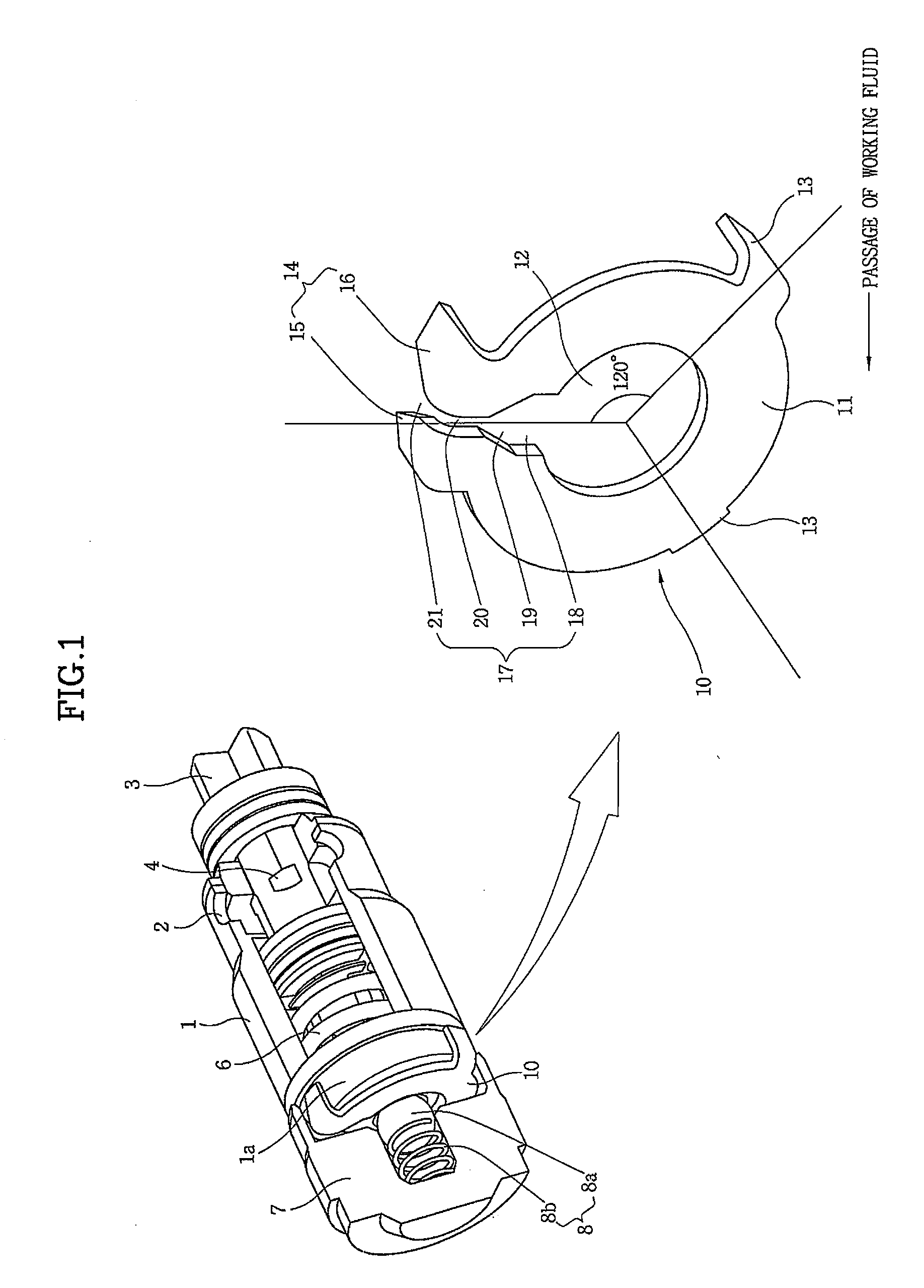
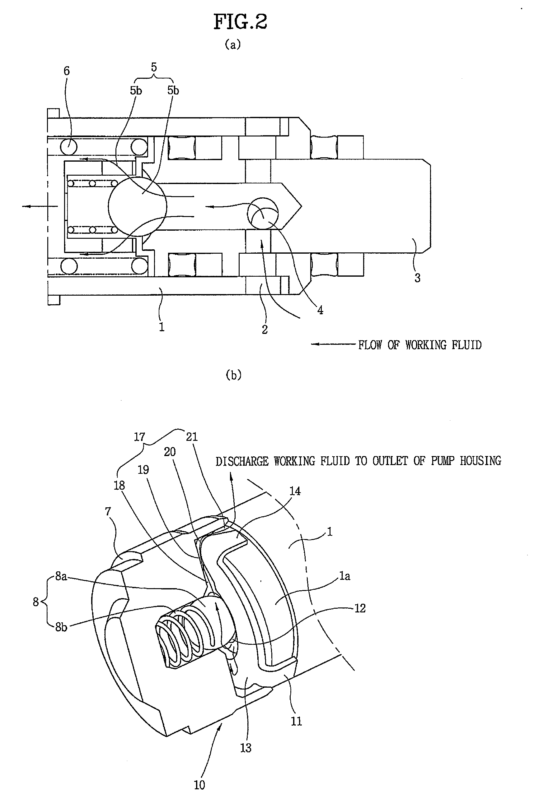
[0020]FIG. 1 is a view showing the structure of a pulsating pressure decreased type control valve for a vehicle slip control system according to an embodiment of the present invention. An oil control pump, which pumps and circulates oil used as a working fluid, of an electronically controlled brake system according to an embodiment of the present invention includes a sleeve 1, a piston 3, an inlet check valve 5, an outlet check valve 8, and an orifice 10. Sleeve 1 is fixed to a pump housing and provides a working fluid passage in the inside thereof. Piston 3 is elastically supported in sleeve 1 by an inner spring 6, and allows the working fluid to flow into the inside thereof during the operation of the pump. Inlet check valve 5 is provided at the front end of piston 3 so as to discharge the working fluid into sleeve 1 by the pressure of the working fluid flowing into piston 3. Outlet check valve 8 is received in a cap 7 fixed to an end of sleeve 1, and opens or closes a discharge p...


PUM


Abstract

The present invention provides a pulsation pressure decreased type pump. When an oil pump that is driven by a motor during the operation of an electronically controlled brake system discharges a working fluid, the working fluid passes through an annular orifice provided at a position where the working fluid is discharged and is then discharged to an outlet of a pump housing through an outflow channel formed in the orifice so as to decrease a pulsating pressure using a piston reciprocated by a cam. Therefore, it is possible to decrease a pulsating pressure generated in the pump from 20 bar to 5 bar or less.

Description

CROSS-REFERENCE TO RELATED APPLICATIONS[0001]The present application is based on, and claims priority from, Korean Application Serial Number 10-2007-0059757, filed on Jun. 19, 2007, the disclosure of which is hereby incorporated by reference herein in its entirety.FIELD OF THE INVENTION[0002]The present invention relates to a pump for a vehicle slip control system, and more particularly, to a pulsation pressure decreased type pump.BACKGROUND OF THE INVENTION[0003]In general, a brake of a vehicle is used to stop a vehicle or reduce the speed of a vehicle by transmitting a braking pressure, which is a hydraulic pressure, to a wheel brake on the basis of the operation of a brake pedal. Since a running vehicle is forcibly stopped by the brake, the vehicle occasionally is slipped due to the braking pressure or road conditions during braking.[0004]A brake, which electronically controls the braking pressure of the wheel brake, has been widely used to prevent the slip from occurring. That i...

Claims


Application Information

Patent Timeline
Patent Type & Authority Applications(United States)
IPC IPC(8): F04B11/00
CPCB60T8/4031F04B11/0091B60T8/40F04B17/00
Inventor KIM, YOUNGKYU
Owner HYUNDAI MOBIS CO LTD
Learn More