Electronically controlled hydraulic brake system

A technology of hydraulic braking and electronic control, applied in the direction of brakes, etc., can solve problems such as low flow rate, discomfort of passengers or drivers, and uncomfortable noise

Inactive Publication Date: 2006-08-23
TOYOTA JIDOSHA KK
View PDF2 Cites 21 Cited by
  • Summary
  • Abstract
  • Description
  • Claims
  • Application Information

AI Technical Summary

Problems solved by technology

When meeting at this junction, a pressure pulse occurs and, due to the lower flow rate in the rear pressure reduction channel than in the front pressure reduction channel, this pressure pulse is transmitted to the rear pressure reduction channel than to the front pressure reduction channel. The pressure reduction channel is more intense, or a pressure pulse occurs in the front pressure reduction channel and is transmitted to the rear pressure reduction channel due to a lower flow rate in the rear pressure reduction channel than in the front pressure reduction channel. The pressure reducing channel is more intense than that transmitted to the front pressure reducing channel, creating a noise that is uncomfortable for the occupants or driver of the vehicle
[0006] Furthermore, there is also the possibility that pressure pulses are transmitted not only to the rear pressure reduction channel, but also to the front pressure reduction channel, but the noise generated in the rear pressure reduction channel is greater than in the front pressure reduction channel The noise produced, or at least the tendency to be more uncomfortable to the passengers or driver in the rear pressure reducing passages than in the front pressure reducing passages

Method used


Image

  • Electronically controlled hydraulic brake system
  • Electronically controlled hydraulic brake system
  • Electronically controlled hydraulic brake system

Examples


Embodiment Construction

[0068] Hereinafter, several presently preferred embodiments of the invention defined by the appended claims will be described in detail with reference to the accompanying drawings. The present invention is not limited to the details of the embodiments described below, but can be implemented with various modifications, including the modes described above, that will occur to those skilled in the art.

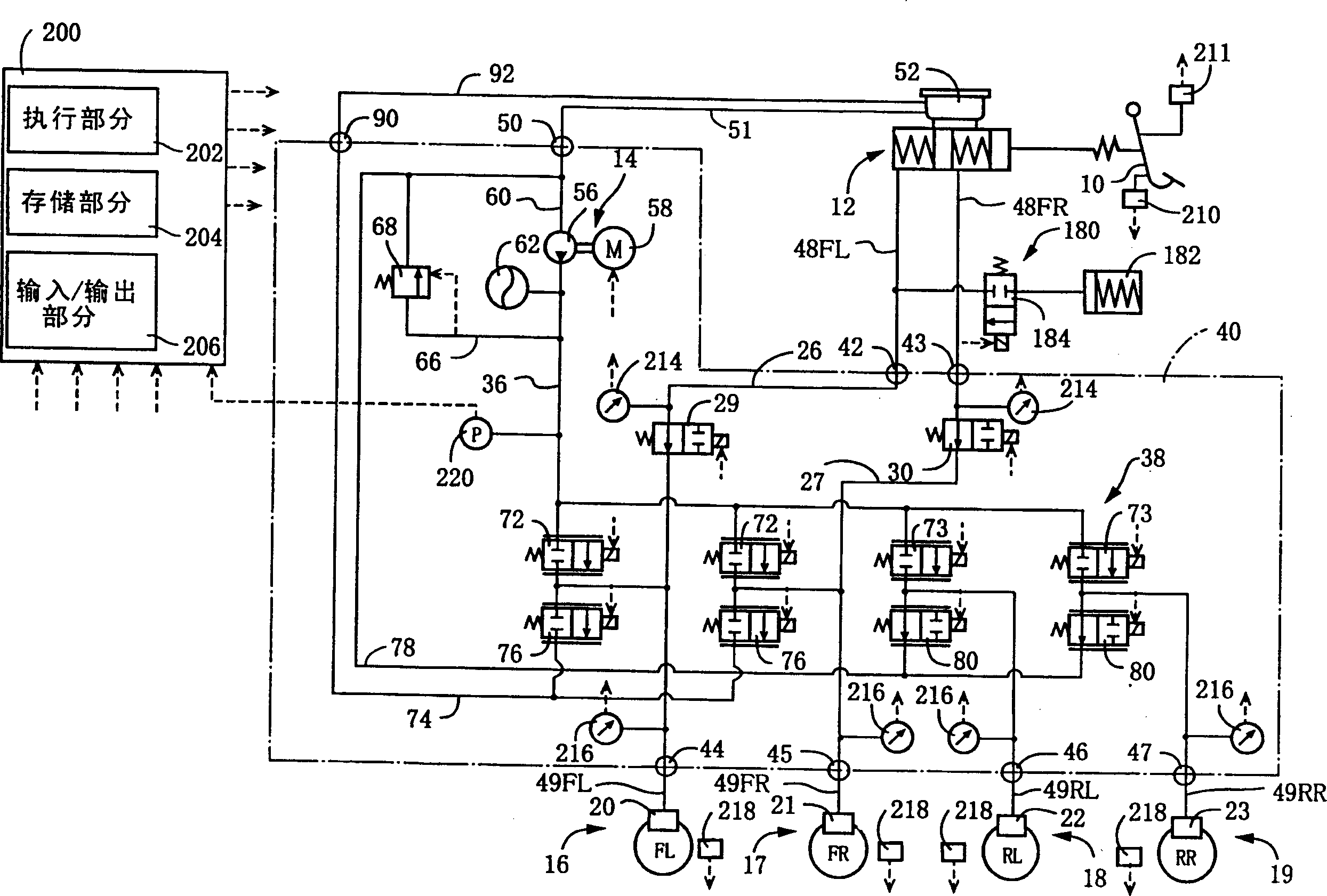
[0069] first reference figure 1, the electronically controlled hydraulic brake system according to the first embodiment will be described. This brake system includes a brake pedal 10 as a brake operating member, a master cylinder 12, a power-operated hydraulic pressure source 14 for each wheel (ie, left front wheel, right front wheel, left rear wheel, and right rear wheel) The four brakes 16-19. Brakes 16, 17 are for the left and right front wheels, and brakes 18, 19 are for the left and right rear wheels. The brakes 16-19 are hydraulic brakes operated by hydraulic pressure in ...


PUM


Abstract

An electronically controlled hydraulic brake system comprising: a brake operating member; a reservoir containing a brake fluid; a front and a rear wheel cylinder; a front and a rear pressure-increase valve; a front and a rear pressure-decrease valve; a power-operated pressure source; a front and a pressure-decrease passage respectively connecting the front and rear pressure-decrease valves with the reservoir; an operating state detecting device detecting an operating state of the brake operating member, based on which the brake fluid is (i) supplied to the front and rear wheel cylinders from the power-operated pressure source by operation of the front and rear pressure-increase valves, so as to increase pressure in the front and rear wheel cylinders, and (ii) discharged from the front and rear wheel cylinders to the reservoir via the front and rear pressure-decrease passages, by operation of the front and rear pressure-decrease valves so as to decrease the pressure in the front and rear wheel cylinders; and pulse transmission restraining means restraining transmission of a pressure pulse from the brake fluid at a junction between the front and rear pressure-decrease passages to the brake fluid in the rear pressure-decrease passage.

Description

technical field [0001] The present invention relates to a hydraulic braking system for a motor vehicle, and more particularly to an electronically controlled hydraulic braking system in which the hydraulic pressure in the wheel cylinder of the brake for braking the rotation of the wheels of the motor vehicle is controlled by an electronic control unit . Background technique [0002] As disclosed in the specification of JP-A-2002-541010, there is known a type of electronically controlled hydraulic brake system in which the operating state of the brake operating member is detected by an operating state detecting device, and based on the detected operation state to control the pressure in the front wheel cylinder for the front wheels and the pressure in the rear wheel cylinder for the rear wheels. That is, when the pressure in the wheel cylinders is to be increased, the brake fluid is supplied from the power-operated hydraulic pressure source to the front and rear wheel cylind...

Claims


Application Information

Patent Timeline
Patent Type & Authority Applications(China)
IPC IPC(8): B60T8/36
CPCB60T8/368B60T8/4081
Inventor 山本贵之
Owner TOYOTA JIDOSHA KK
Why Eureka
Try Eureka