Liquid distribution apparatus employing a check valve for distributing liquid into a seed furrow

a technology of liquid distribution apparatus and check valve, which is applied in the field of agricultural seed planters and drills, can solve the problems of affecting the location of seeds, affecting the final crop yield, and burning seeds, and affecting the growth of plants and the effect of final crop yield

Inactive Publication Date: 2005-12-01
SCHAFFERT PAUL E
View PDF66 Cites 23 Cited by
  • Summary
  • Abstract
  • Description
  • Claims
  • Application Information

AI Technical Summary

Benefits of technology

[0016] Another aspect of the invention involves an extension for use with a planter to interact with seeds distributed from the planter. The planter includes at least one liquid supply hose coupled with a pump configured to deliver the liquid to the liquid supply hose under pressure. The seed furrow typically has a centrally located bottom portion and a first sidewall and a second sidewall. The first sidewall and the second sidewall extend upwardly and outwardly from the centrally located bottom portion of the furrow. The extension comprises means for engaging seeds distributed from the planter, means for distributing liquid from the liquid supply hose to the furrow, and means for substantially stopping the flow of the liquid into the furrow when the pump is not delivering the liquid under pressure to the liquid supply hose.

Problems solved by technology

However, as the seeds descend through the seed tube, they are prone to bouncing, which ultimately affects where the seeds lie in the furrow.
In addition, the seeds may bounce off the soil when they land in the furrow, which also affects where the seeds lie in the furrow.
However, problems can arise when providing liquid directly into the furrow along with the seeds.
Drenching the seed in fertilizer may result in burning the seed which has a negative impact on plant growth and the ultimate crop yield.
The liquid fertilizer disks, however, are very expensive, require large amounts of fertilizer because of the remote location from the seeds, and do not provide for in-furrow distribution of liquid.
There are several potential disadvantages and problems with the liquid dispensing devices illustrated in FIGS. 1A-1G.
One potential problem is that these liquid dispensing devices have small diameter openings for the liquids to pass through.
Heavier fertilizers in some instances do not flow evenly from these small diameter outlets.
Additionally, when used with heavy materials such as fertilizer that require a larger opening to pass through, these devices may plug-up and stop the flow of material.
When plugging occurs, inadequate amounts of product will be placed in the furrow by the plugged lines.
Another problem is that to avoid plugging, the liquid must be diluted with water.
Diluting the fertilizer, however, causes problems for the application because to obtain the appropriate amount of liquid in the furrow a greater volume of liquid (fertilizer diluted with water) has to be delivered into the furrow through the smaller holes in the delivery system.
The greater volume of liquid in the furrow additionally produces wetness in the furrow that can cause the press wheels to build up with mud, which, in turn, leads to closing problems with the press wheels.
Besides the unwanted effects caused by drenching the seeds in some liquids, putting any fertilizer in such close proximity to the seed, especially in drier soil, draws the moisture out of the soil around it, pulling it in close to the seed.
If dry soil conditions persist, then the seed may run out of moisture for the tap root and nodule roots to pick up, which may stunt the growth of the emerging crop and in some instances result in the death of the crop.
In addition, oftentimes the proper application of a liquid into the furrow has been complicated by ceasing the flow of the liquid from the liquid supply tank, such as by turning off a pump or distributor system tasked with transferring the liquid under pressure from the tank to the furrow.
Under such conditions, an inordinate amount of liquid continues to flow after the pump or distributor system is shut off until the tube from the supply tank is empty.
Conversely, when the pump is restarted, a significant amount of time normally elapses until liquid is once again flowing into the furrow.

Method used


Image

  • Liquid distribution apparatus employing a check valve for distributing liquid into a seed furrow
  • Liquid distribution apparatus employing a check valve for distributing liquid into a seed furrow
  • Liquid distribution apparatus employing a check valve for distributing liquid into a seed furrow

Examples


Embodiment Construction

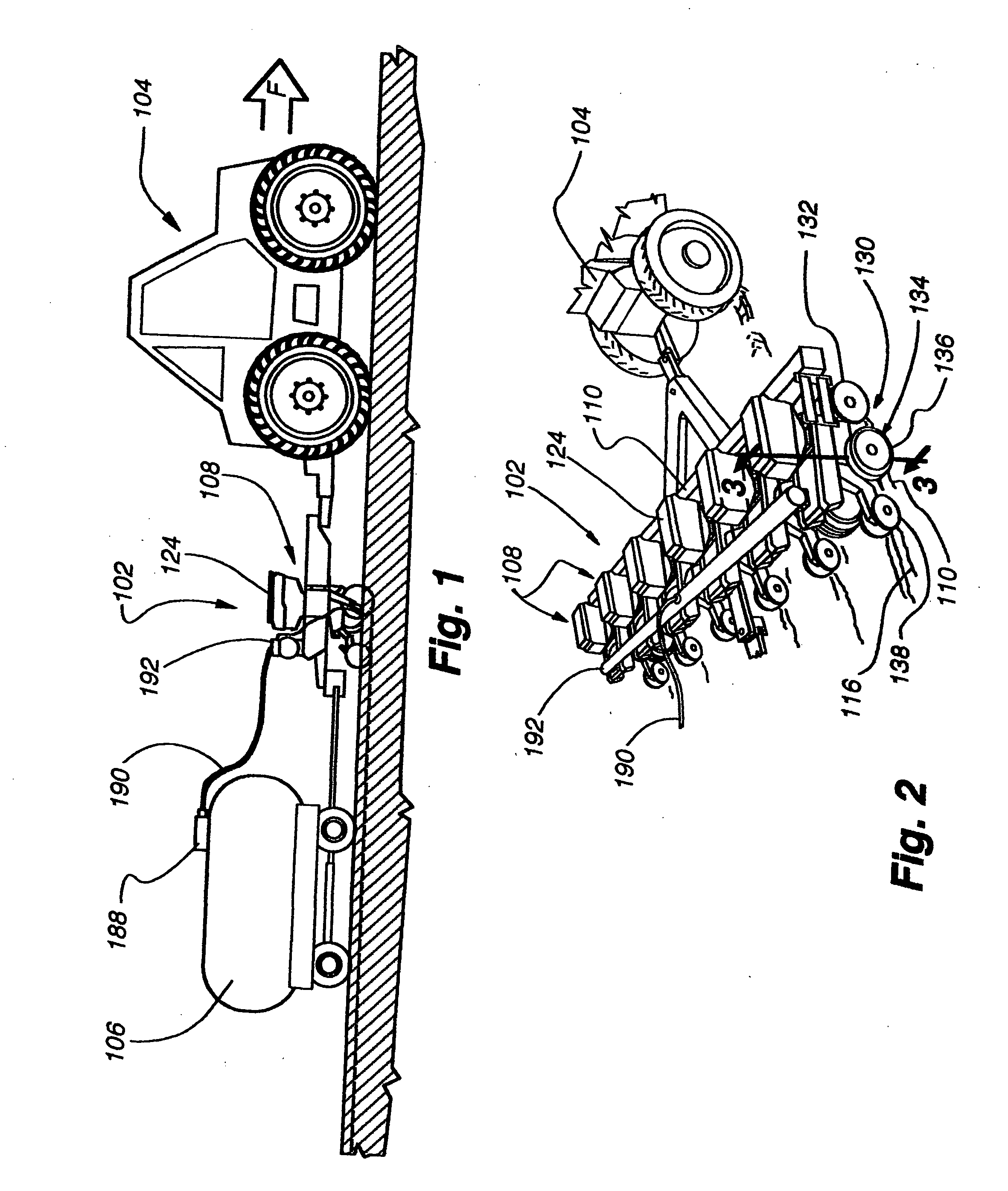
[0116] While various embodiments of the liquid distribution apparatus can be used with a variety of planters, drills and liquid supply devices, it will be initially described as used with a double disk furrow opener style agricultural planter 102 pulled behind a tractor 104. Furthermore, the liquid distribution apparatus will be described in a configuration wherein a large liquid container 106 is pulled behind the planter 102 providing a liquid supply to the liquid distribution apparatus through a liquid supply hose 190. Typically, a pump supplies liquid to the hoses. The liquid container 106, however, is oftentimes integrated with the planter 102 or the tractor 104. Nonetheless, the liquid distribution apparatus functions equally well regardless of the location of the liquid container 106.

[0117] The agricultural planter 102, shown in FIGS. 1-3, typically includes a number of planter row units 108 mounted on a main frame member 110. The planter 102 is pulled in a forward direction ...


PUM


Abstract

Aspects of the present invention involve an extension adapted to extend from a planter, such as the seed tube portion of the planter, into a seed furrow in order to engage seeds being deposited therein, where such engagement may involve deflecting the seeds toward the vertex region of the furrow and / or firming the seeds in the furrow. The extension includes or supports a fluid distribution arrangement such as a hose or the like, which may be separate or integral with the liquid supply hose of a planter. The fluid distribution arrangement is adapted to supply fluid, such as liquid fertilizer, insecticide, water, etc., to the furrow. A valve is provided in the fluid flow path in the region of the fluid distribution arrangement to control the distribution of fluid to the furrow. The valve may be a check valve that allows fluid flow therethrough when fluid pressure exceeds a value such that the valve opens, and prevents fluid flow when the pressure decreases below the valve activation pressure.

Description

CROSS-REFERENCES TO RELATED APPLICATIONS [0001] This application is a non-provisional application claiming priority to U.S. provisional patent application No. 60 / 583,971 titled “Liquid Distribution Apparatus Employing a Check Valve for Distributing Liquid Into a Seed Furrow” filed on Jun. 28, 2004, and is also a continuation-in-part claiming priority to application Ser. No. 10 / 819,565 entitled “Liquid Distribution Apparatus for Distributing Liquid into a Seed Furrow” filed Apr. 6, 2004, which is a continuation-in-part of application Ser. No. 10 / 228,688 entitled “Liquid Distribution Apparatus for Distributing Liquid into a Seed Furrow” filed Aug. 26, 2002, now U.S. Pat. No. 6,763,773, which is a continuation-in-part of Ser. No. 09 / 832,740 entitled “Liquid Distribution Apparatus for Distributing Liquid Into a Seed Furrow” filed Apr. 9, 2001, now U.S. Pat. No. 6,453,832 B1, which is a non-provisional application claiming priority to provisional application 60 / 195,942, and which is a co...

Claims


Application Information

Patent Timeline
Patent Type & Authority Applications(United States)
IPC IPC(8): A01C13/00A01C23/02
CPCA01C5/06A01C5/062A01C23/025A01C7/201A01C7/06A01C5/068A01C5/064
Inventor SCHAFFERT, PAUL E.
Owner SCHAFFERT PAUL E
Why Eureka
Try Eureka