Individual adaptive pressure increasing and decreasing control method for electronic sphygmomanometer

An electronic sphygmomanometer and control method technology, applied in the direction of cardiac catheterization, etc., can solve the problems of low accuracy of results, discount of comfort, slow decompression speed, etc., and achieve the effects of obvious envelope characteristics, improved comfort, and appropriate quantity

Inactive Publication Date: 2013-04-24
邓亲恺 +1
View PDF0 Cites 25 Cited by
  • Summary
  • Abstract
  • Description
  • Claims
  • Application Information

AI Technical Summary

Problems solved by technology

On the one hand, the decompression speed at the beginning is too fast, and the number of pulse waves between the mean pressure and the systolic pressure is too small; Long, resulting in unavoidable shortcomings and problems: For example, the measurer's arm is prone to congestion and paralysis, and there is an obvious sense of pressure, which greatly reduces the comfort, and the decompression speed is uneven, and the pulse wave envelope is not obvious, resulting in unstable measurement results. low precision
At present, in the amplification and conditioning circuit, the resistance value of the amplification resistor is adjusted through an analog switch. The adjustment process requires an external additional circuit, which requires a certain hardware cost, and also increases the size and power consumption of the instrument.

Method used


Image

  • Individual adaptive pressure increasing and decreasing control method for electronic sphygmomanometer
  • Individual adaptive pressure increasing and decreasing control method for electronic sphygmomanometer
  • Individual adaptive pressure increasing and decreasing control method for electronic sphygmomanometer

Examples


Embodiment Construction

[0034] Below, in conjunction with accompanying drawing and specific embodiment, the present invention is described further:

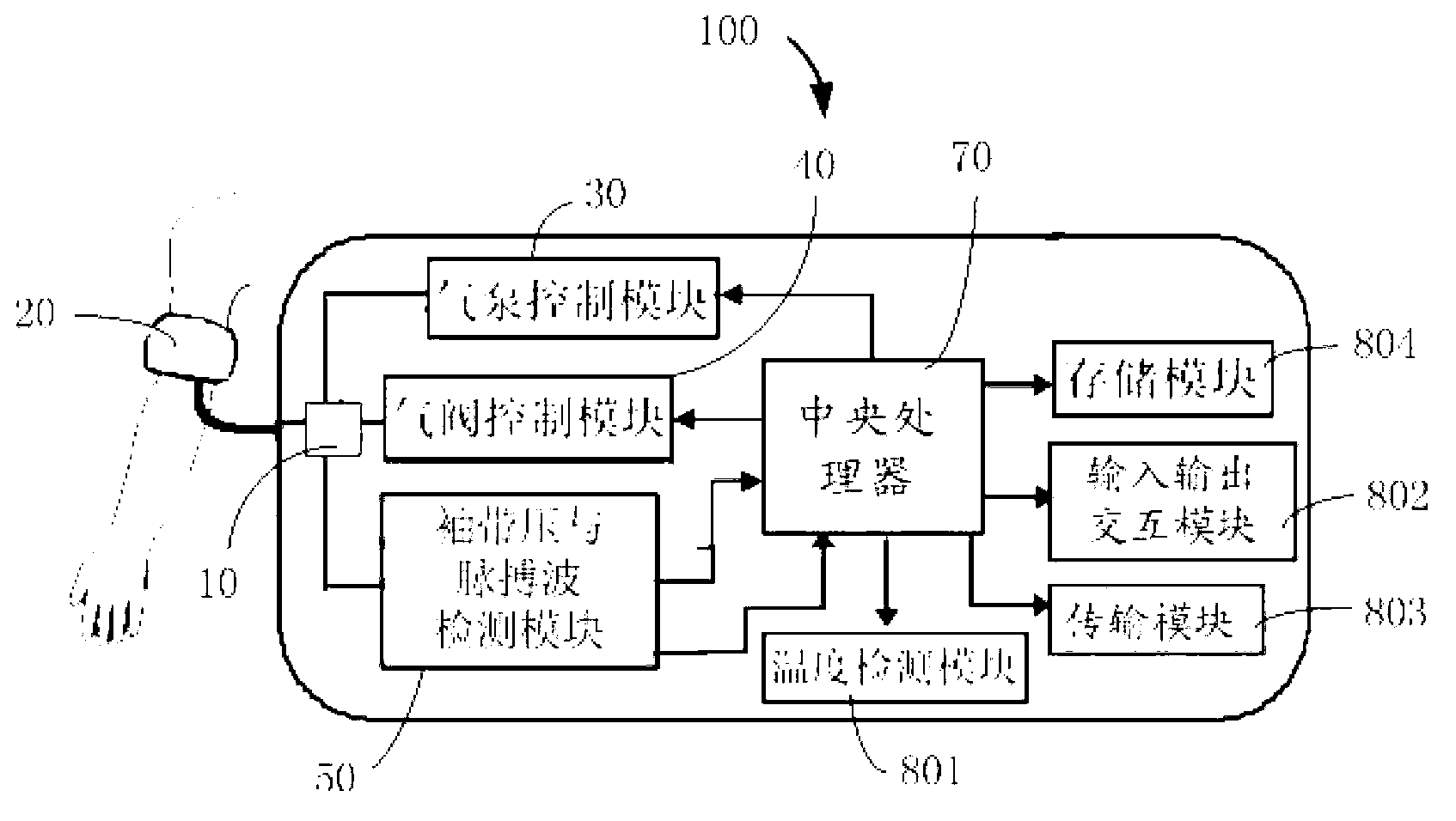
[0035] Such as figure 1 Shown is a schematic diagram of an electronic sphygmomanometer implementing the electronic sphygmomanometer individual self-adaptive acceleration and decompression control method of the present invention. The electronic sphygmomanometer 100 includes a connector 10, a cuff 20, an air pump control module 30, an air valve control module 40, a cuff pressure and pulse wave detection module 50, a central processing unit 70, a temperature detection module 801, and an input-output interaction module. 802, a transmission module 803, a storage module 804, and the like. The air pump control module 30 , the air valve control module 40 , and the cuff pressure and pulse wave detection module 50 are respectively connected to the communicator 10 and the central processing unit 70 . The temperature detection module 801 , the input-output interac...


PUM


Abstract

The invention discloses an individual adaptive pressure increasing and decreasing control method for an electronic sphygmomanometer. The method includes: continuously inflating a cuff sleeved on an upper arm for pressure increasing; detecting pulse wave signals and cuff pressure signals; calculating mean pressure Pv and heart rate S according to the pulse wave signals during pressure increasing, calculating systolic pressure Ps according to the mean pressure Pv, and setting the maximum valve Pm of cuff pressure increasing; when the pressure of the cuff reaches the maximum value Pm, by a control air valve, performing individual adaptive constant-speed pressure decreasing until pressure decreasing is completed and the control air valve is completely opened to empty air. By the individual adaptive pressure increasing and decreasing control method for the electronic sphygmomanometer and the electronic sphygmomanometer, high-quality pulse wave signals with moderate pulse waves, reasonable amplitude and evident envelop features, a premise is provided for further identification and determining of blood pressure parameters, and comfortableness of a to-be-tested person is improved during the whole test. In addition, the method is high in individual adaptive measuring capability.

Description

technical field [0001] The invention relates to the technical field of human physiological signal detection and signal processing, in particular to an electronic sphygmomanometer individual self-adaptive acceleration and decompression control method and an electronic sphygmomanometer applying the method. Background technique [0002] The electronic sphygmomanometers currently on the market are generally based on the principle of the oscillometric method (oscillation method), and most electronic sphygmomanometers based on the oscillometric method first pressurize (inflate) and then decompress (deflate), and then detect the pulse during the decompression process wave signal to realize the measurement of blood pressure parameters, that is, measurement during decompression (MWD technology). For electronic sphygmomanometers based on the principle of the oscillometric method, the measurement results should be carried out under the control of a reasonable decompression speed (rate)...

Claims


Application Information

Patent Timeline
Patent Type & Authority Applications(China)
IPC IPC(8): A61B5/0225
Inventor 邓亲恺冯学技郭劲松梁妃学
Owner 邓亲恺
Why Eureka
Try Eureka