Slider tester and method for testing slider

Active Publication Date: 2009-10-29
NHK SPRING CO LTD
View PDF5 Cites 4 Cited by
  • Summary
  • Abstract
  • Description
  • Claims
  • Application Information

AI Technical Summary

Benefits of technology

[0012]The present invention provides a slider tester capable of safel

Problems solved by technology

Thus, testing a plurality of sliders is not efficient and requires a long time.

Method used


Image

  • Slider tester and method for testing slider
  • Slider tester and method for testing slider
  • Slider tester and method for testing slider

Examples


Example

[0028]An embodiment of the present invention will now be described with reference to FIGS. 1 to 9.

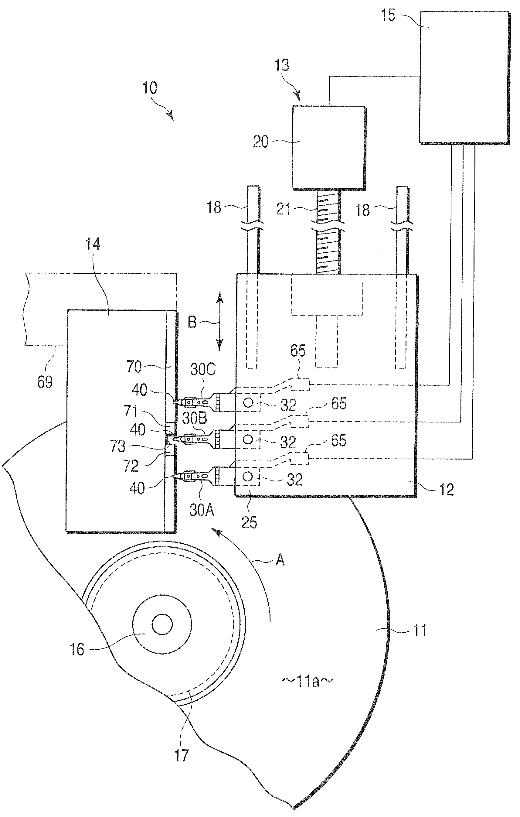
[0029]A slider tester 10 shown in FIG. 1 includes a disk 11 that functions as a recording medium, movable table 12, table drive mechanism 13, guide member 14, signal processing section 15, etc. The disk 11 has a recording surface 11a on which data can be magnetically recorded. The disk 11 is rotated in a fixed direction (indicated by arrow A in FIG. 1) by a rotational mechanism 17 with a spindle 16.

[0030]The movable table 12 can reciorocate transversely along guide members 18 relative to the track of the recording surface 11a of the disk 11 (or in the direction indicated by arrow B in FIG. 1). An example of the table drive mechanism 13 includes a servomotor 20 and ball screw 21. As the servomotor 20 rotates, the movable table 12 can move for a desired distance along the track width. The signal processing section 15 that functions as a controller can control the table drive mechanism 13 ...


PUM

PropertyMeasurementUnit
Distanceaaaaaaaaaa

Abstract

A slider tester includes a disk, movable table, table drive mechanism, guide member, etc. A plurality of suspensions are mounted on the movable table. A slider is mounted on each suspension. A guide member can support respective lift tabs of the suspensions. The guide member includes a first guide surface, second guide surface, and opening arranged in a track width direction of the disk. When any of the lift tabs gets into the opening as the movable table moves in the track width direction of the disk, the slider is dropped toward a recording surface of the disk.

Description

CROSS-REFERENCE TO RELATED APPLICATIONS[0001]This application is based upon and claims the benefit of priority from prior Japanese Patent Application No. 2008-117774, filed Apr. 28, 2008, the entire contents of which are incorporated herein by reference.BACKGROUND OF THE INVENTION[0002]1. Field of the Invention[0003]This invention relates to a slider tester for inspecting a slider of a disk drive used in an information processing apparatus or the like.[0004]2. Description of the Related Art[0005]A hard disk drive (HDD) includes a disk that functions as a recording medium, disk drive suspension (hereinafter simply referred to as the suspension), actuator arm on which the suspension is mounted, etc. Data is magnetically recorded on the disk. A slider is mounted on the distal end portion of the suspension. This slider is provided with a magnetoelectric element used to access data to a recording surface of the disk, that is, an element for writing or reading data.[0006]The suspension in...

Claims


Application Information

Patent Timeline
IPC IPC(8): G11B27/36
CPCG11B5/455Y10T29/49025Y10T29/49037Y10T29/49032Y10T29/53165Y10T29/49027
Inventor NOJIMA, AKIRA
Owner NHK SPRING CO LTD
Why Eureka
Try Eureka