
Method and apparatus for testing characteristics of a furnace melt

Inactive Publication Date: 2010-04-27
PROCESS TECH INT
View PDF20 Cites 5 Cited by
  • Summary
  • Abstract
  • Description
  • Claims
  • Application Information

AI Technical Summary

Benefits of technology

[0022]The invention provides a method and apparatus for testing characteristics of molten metal in a furnace. Preferably, the method and apparatus provide the safe and efficient testing of the temperature and composition of molten metal during the melt cycle of the metal.
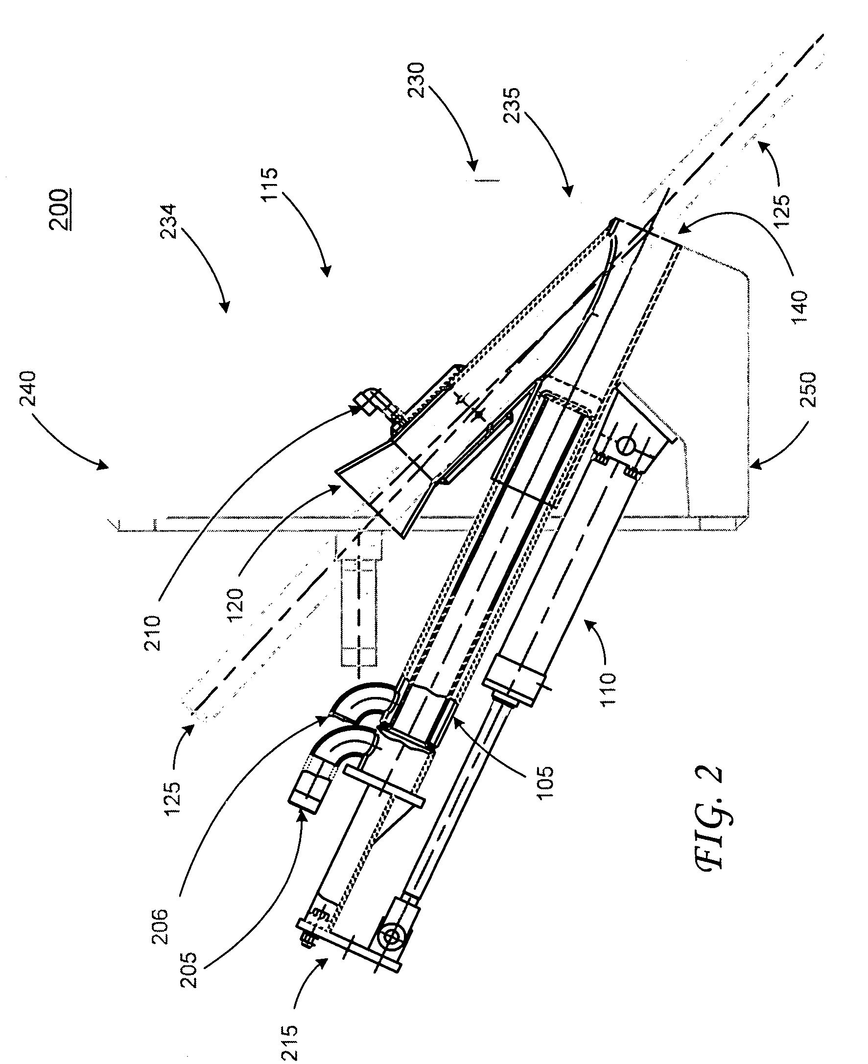
[0027]According to another aspect of the present invention, a furnace probe apparatus for use in an electric arc furnace comprises a furnace probe aperture plug adapted for insertion into a furnace probe aperture and a furnace probe aperture plug reciprocator for moving the furnace probe aperture plug. Preferably, the furnace probe aperture plug reciprocator is coupled to the furnace probe aperture plug and adapted to move the plug between a retracted position and an inserted position relative to the furnace probe aperture. When the furnace probe aperture plug is in an inserted position, it closes the furnace probe aperture and prevents slag and other debris from entering the furnace probe apparatus. When the furnace probe aperture plug is in a retracted position, it allows passage of a furnace probe through the furnace probe aperture.
[0029]According to another aspect of the present invention, the furnace probe apparatus mounting enclosure is fluid cooled and adapted to protect the furnace probe aperture plug and the furnace probe from the harsh environment of the furnace.
[0031]According to yet another aspect of the present invention, the mounting enclosure includes a deflector for deflecting scrap charged in the furnace away from the furnace probe and aperture plug. Preferably, the deflector is a porch sloped toward the inside of the furnace. Additionally, the mounting enclosure may include corrugations for retaining slag. The slag helps insulate the mounting device from the heat of the furnace.

Problems solved by technology

Unfortunately, there are several challenges that must be surmounted to determine whether the melt is ready for tapping.
Additionally, due to the high temperature, it is not practical to install a permanent temperature gauge in the furnace to monitor the temperature of the molten metal bath.
Unfortunately, there are several drawbacks to measuring the temperature through the open slag door.
For example, when the door is open, a large amount of heat can escape the furnace.
This manual operation puts the operator at great risk of injury.
Today, some steel plants and foundries still use this manual procedure because most alternative systems are very costly.
Each year, operators are seriously injured or even killed while taking furnace measurements manually.
These injuries typically occur when slag volume increases quickly in the furnace and overflows, thereby causing injury to the operator.
The oxidizable elements in the slag or steel will react with the active oxygen in the steel bath and create, very quickly, a large amount of combustible gasses.
In addition, when the combustible gases created in this reaction are exiting the furnace through the slag door, they rapidly combust with the air outside of the furnace thus increasing the intensity of the reaction.
Such reactions occur so quickly that it creates an explosive effect.
Tragically, if such reactions occur while the slag door is open for a manual measurement, the slag boil can overflow the furnace and cause great harm to the operator.
Now, many furnace operators use a large, and expensive, mobile device for inserting probes into the furnace.
Since the slag door must remain clear for removing slag from the furnace, a dedicated temperature probe insertion tool can not be installed adjacent to the slag door.
Since any scrap trapped in the opening is pushed into the melt adjacent to the door, a probe inserted through the door can not easily measure the temperature of the melt.
This practice adds additional time to the melting phase, and therefore additional expense, to the steel making process.
There are other potential options available for insertion of the temperature probe, but each has significant drawbacks and is not typically used in the industry.
Unfortunately, there is not a good location for providing such opening.
If the opening were provided low in the furnace, close to the melt, it would become clogged with slag.
Cleaning the slag from the hole is an onerous task because the slag solidifies on the walls of the furnace and can become quite thick.
Thus, it would be difficult to clean the slag from the opening and insert the temperature probe in an efficient manner.
This solution is also not desirable because the access opening would be far from the melt.

Method used


Image

  • Method and apparatus for testing characteristics of a furnace melt
  • Method and apparatus for testing characteristics of a furnace melt
  • Method and apparatus for testing characteristics of a furnace melt

Examples


Embodiment Construction

[0037]Referring now the drawings, in which like numerals represent like elements, exemplary embodiments of the present invention are herein described.

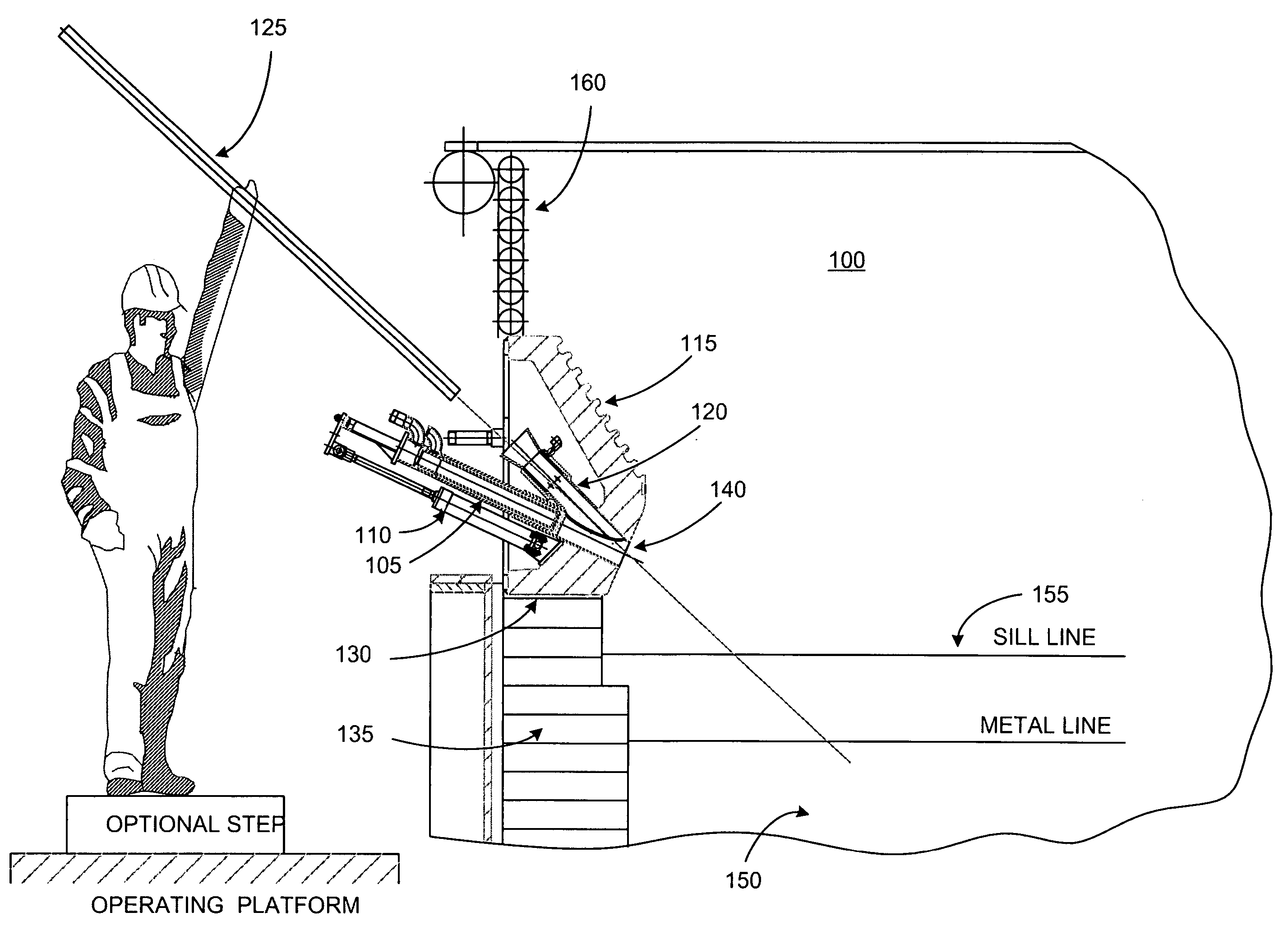
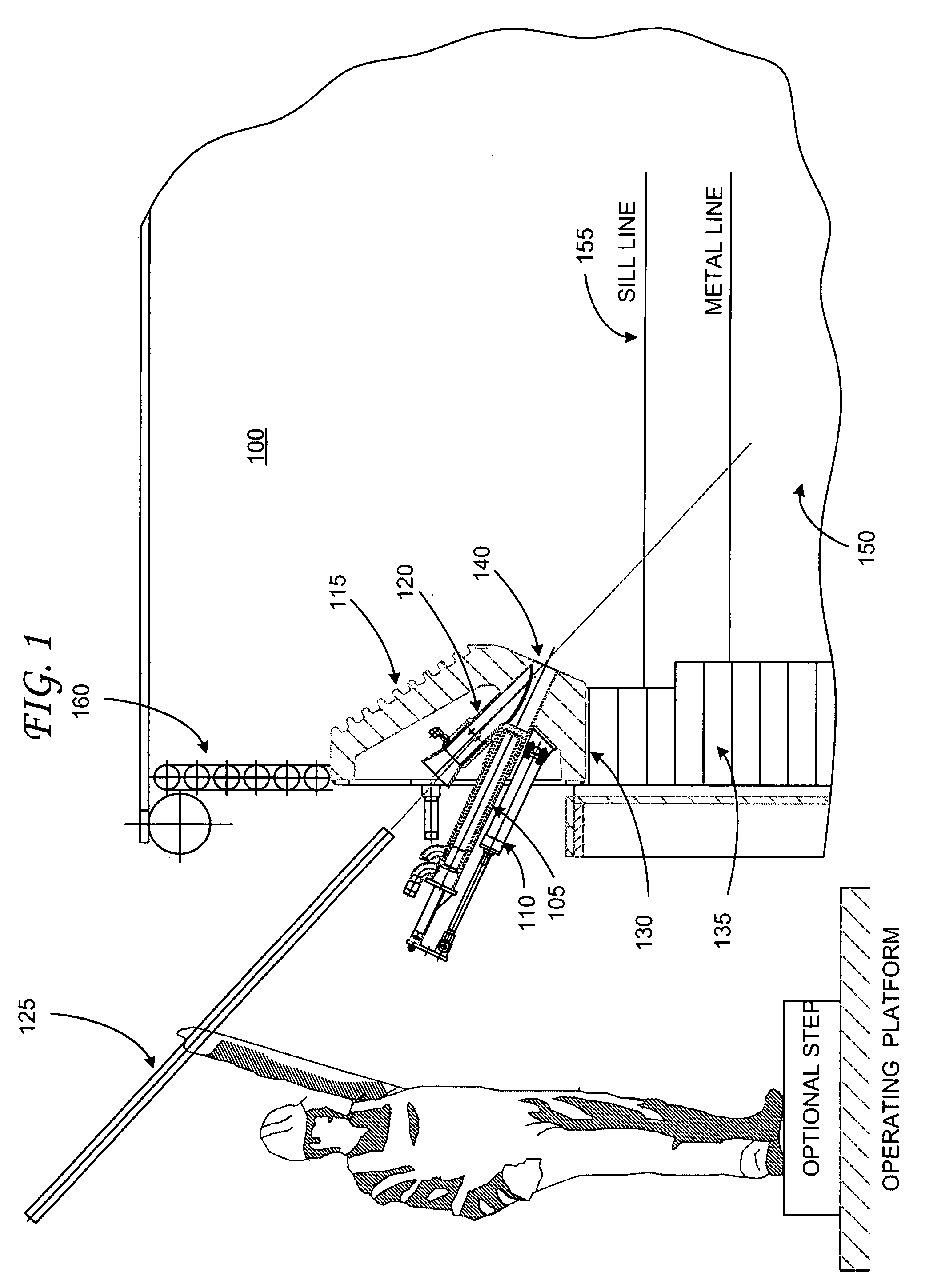
[0038]FIG. 1 is a cross-sectioned side view of an exemplary embodiment a furnace probe apparatus mounted in an electric arc furnace (“EAF”) and which is constructed in accordance with an exemplary embodiment of the invention. In an exemplary embodiment, the EAF 100 melts ferrous scrap, or other iron based materials, by means of an electric arc produced from one or more electrodes to collect a molten metal bath or melt 150 in its hearth. The metal bath level varies significantly during the melting process. The bath level generally begins with a hot heel level, which is the iron melt left from the previous heat. As multiple charges of scrap or other iron base materials are melted, the level rises. The furnace is typically filled to a level about 18 inches down from the sill line 155. Other steel making processes such as DRI melting and t...


PUM

PropertyMeasurementUnit
Angleaaaaaaaaaa
Angleaaaaaaaaaa
Widthaaaaaaaaaa

Abstract

A method and apparatus for testing characteristics of a furnace melt are provided. Preferably, the method and apparatus provide for the safe and efficient testing of metal temperature and composition of molten metal during the melt cycle of the metal. According to one aspect of the invention used in a steel making process in an electric arc furnace, a furnace probe is reciprocated through a furnace probe plug aperture, the furnace probe is retracted from the furnace probe plug aperture, a furnace probe is inserted through the furnace probe plug aperture, the furnace probe is retracted from the aperture, and the furnace probe aperture plug is inserted into the furnace probe plug aperture.

Description

TECHNICAL FIELD[0001]The present invention relates generally to a method and apparatus used in metal melting, refining and processing, and more particularly, a method and apparatus for testing the characteristics of molten metal in a furnace melt.BACKGROUND[0002]Electric arc furnaces (EAFs) make steel by using an electric arc to melt one or more charges of scrap metal, hot metal, iron based materials, or other meltable materials, which is placed within the furnace. Modern EAFs may also make steel by melting DRI (direct reduced iron) combined with the hot metal from a blast furnace. In addition to the electrical energy of the arc, chemical energy is provided by auxiliary burners using fuel and an oxidizing gas to produce combustion products with a high heat content to assist the arc.[0003]If the EAF is used as a scrap melter, the scrap burden is charged by dumping it into the furnace through the roof opening from buckets, which also may include charged carbon and slag forming materia...

Claims


Application Information

Patent Timeline
IPC IPC(8): F27D3/14C21B7/16
CPCC21B7/24C21C5/4673F27B3/205F27B3/225F27D99/0033F27B3/28F27D3/12F27D19/00F27D21/00F27B3/24C21C2005/5288Y02P10/20
Inventor SHVER, VALERY G.
Owner PROCESS TECH INT
Learn More