Transformer test control device

a technology of transformer test and control device, which is applied in the direction of measurement device, electrical testing, instruments, etc., can solve the problems of short circuit or overheating, transformer damage, and deprived customers "downline" therefrom of electrical power and service, and achieve safe and efficient testing

Inactive Publication Date: 2002-09-03
WHITE XENIA BURDETTE
View PDF12 Cites 42 Cited by
  • Summary
  • Abstract
  • Description
  • Claims
  • Application Information

AI Technical Summary

Benefits of technology

It is an object of the invention to provide improved testing equipment for safe and efficient testing of power pole mounted transformers prior to their removal and / or replacement.
It is another object of the invention to reduce the number of pieces of equipment needed for on-site testing of transformers.
It is an additional object of the invention to reduce the exposure to power grid voltages by line personnel.
The variable resistor and the H1 power supply terminal are separated by an operator controllable switch, preferably of the momentary rocker type. This switch will permit the input of alternating current potential to the primary coil of the transformer only after the entire test setup is completed and the operator no longer is touching anything, thus avoiding possible shock to the operator as the test voltage is applied. The conductors to the H1 and H2 terminals of the control assembly may be further bridged, downline from the variable resistor bridge, by a indicator visible to the operator showing if any electrical power is being supplied to the test assembly. Alternatively, a visual indicator may be placed in the high voltage line either immediately prior to the H1 control assembly terminal or between the variable resistor tap and the H1 control assembly terminal connection. Moreover, a visual indicator is connected inline with a fuse socket or holder that also can be used as a fuse tester. The fuse socket may be in addition to a fuse socket in a high voltage conductor and so is disposed for safety purposes.
For ease in using a voltmeter in the adverse conditions frequently encountered by a lineman to repair power lines and the like, a pair of terminals is provided to receive the test leads for connection to the output terminals: X1 and X2; X1 and X3; or X2 and X3 of the transformer. A multimeter preferably is used to accurately read the output voltages from the secondary coil of the transformer. So that the hands of the operator are freed from holding a multimeter or the multimeter test probes against the X1, X2 and / or X3 terminals the multimeter leads are connected into multimeter connecting terminals on the test control assembly. Such lead connection also permits the operator to activate the test switch, Multimeter test leads are clipped to the selected transformer terminals. The pair of terminals provided to receive the multimeter test leads from the secondary coil connections of the transformer are connected directly to the multimeter connecting terminals on the test control assembly. This facilitates the use of a multimeter and typically is found on a utility line truck.
Supplying electrical power to the test control assembly through an electrical extension cord permits the testing of the transformer either on the electrical utility power pole or in the shop or equipment yard without having to remove the transformer from the pole or move the transformer to a dedicated test station.

Problems solved by technology

From time to time, these transformers may be damaged by natural forces such as lightning strikes or wind damage, animals or birds, and human factors including vehicles knocking down power lines, any of which can lead to short circuits or overheating.
Once a transformer in an electrical power distribution system is damaged and fails, the customers "downline" therefrom are deprived of electrical power and service.
Note, not all of the above causes of power interruption result in a defective transformer.
This may mean that a very high voltage may be impressed on the potentially defective transformer.
Re-powering the transformer with a high voltage may cause the transformer to burn and / or explode, potentially endangering the safety or life of the lineman.
However, a line truck may not have such a lower alternating current voltage source available.
The lineman's safety and ability to perform his job are affected or complicated by adverse weather conditions including high wind and rain during the reconnection to the power grid voltage to the transformer, and reading the output terminal voltages, and the safety measures required when working around such high voltages.
With the connection of the power grid voltage to the transformer H1 and H2 voltage terminals, it is also possible that a defective transformer may explode or catch fire, burning or injuring the lineman, or the cooling oil contained within the case of the transformer may spill and may contaminate both the work site and equipment.
The typical transformer oil is a hazardous material, requiring an environmental cleanup of polluting cooling oil.
The expense of such a procedure is quite high and this approach creates a large demand for manpower and an equipment burden, particularly so if the work must be performed under adverse weather conditions.
Also, this alternative procedure may result in replacing usable transformers and needlessly spending the cost of an unnecessary replacement.
Because all utility line trucks commonly carry a multimeter in their complement of tools and equipment, incorporating a dedicated multimeter into the test control assembly unreasonably may increase the cost although the option to incorporate one remains.

Method used


Image

  • Transformer test control device
  • Transformer test control device
  • Transformer test control device

Examples


Embodiment Construction

AS CONTEMPLATED BY THE INVENTOR

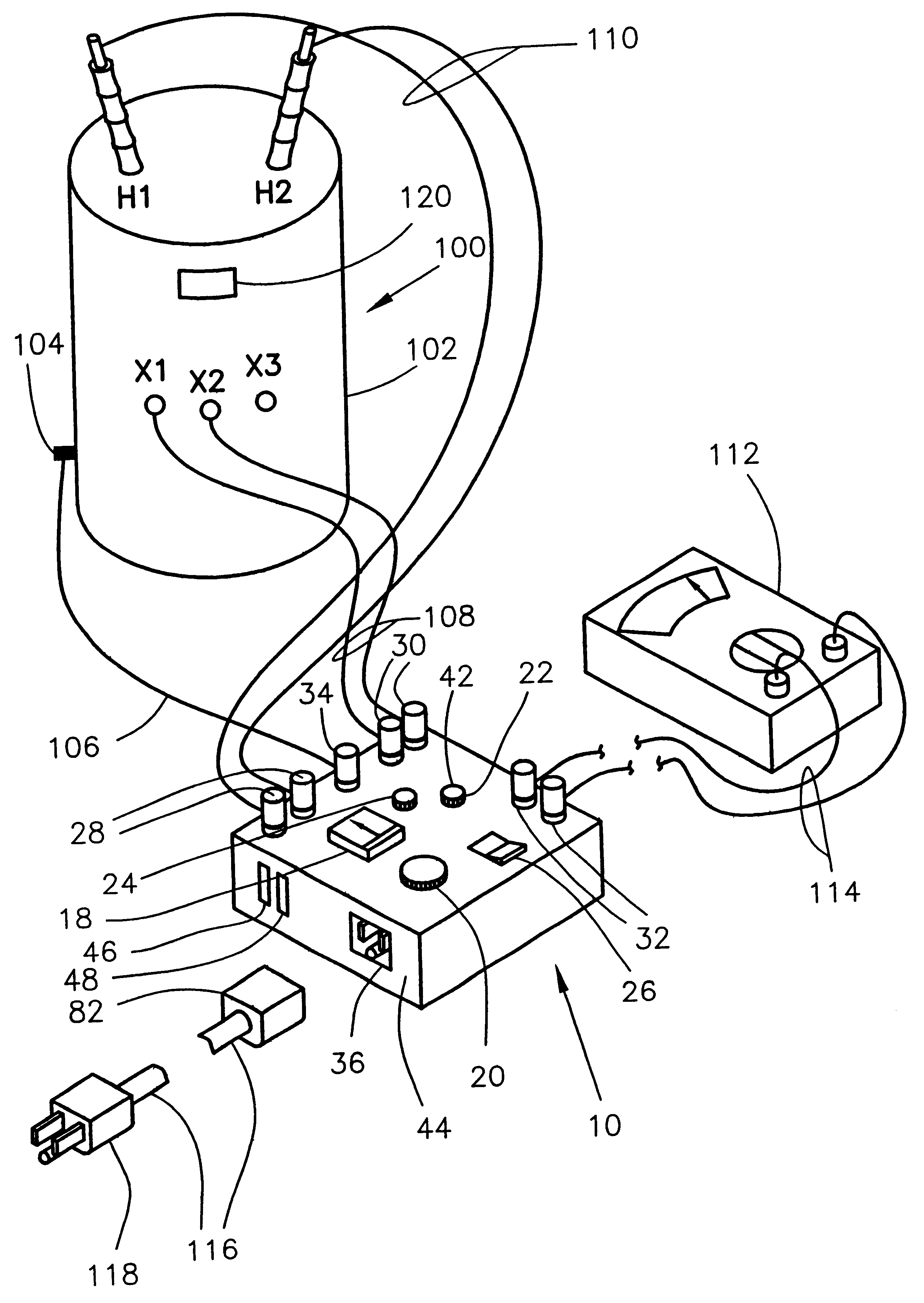
The invention is a test control assembly 10 for testing electrical power distribution transformers of the type used to reduce or step down the power grid transmission voltage to a voltage usable by a residence or business consumer and commonly referred to as house voltage, i.e., 7200 volts or 2400 volts reduced to 120 volts and 240 volts, 277 volts or 480 volts, respectively. The stepped down or reduced output voltages are determined by the ratio of the number of turns of wire in the primary coil to the number of turns of wire in the secondary coils of the transformer.

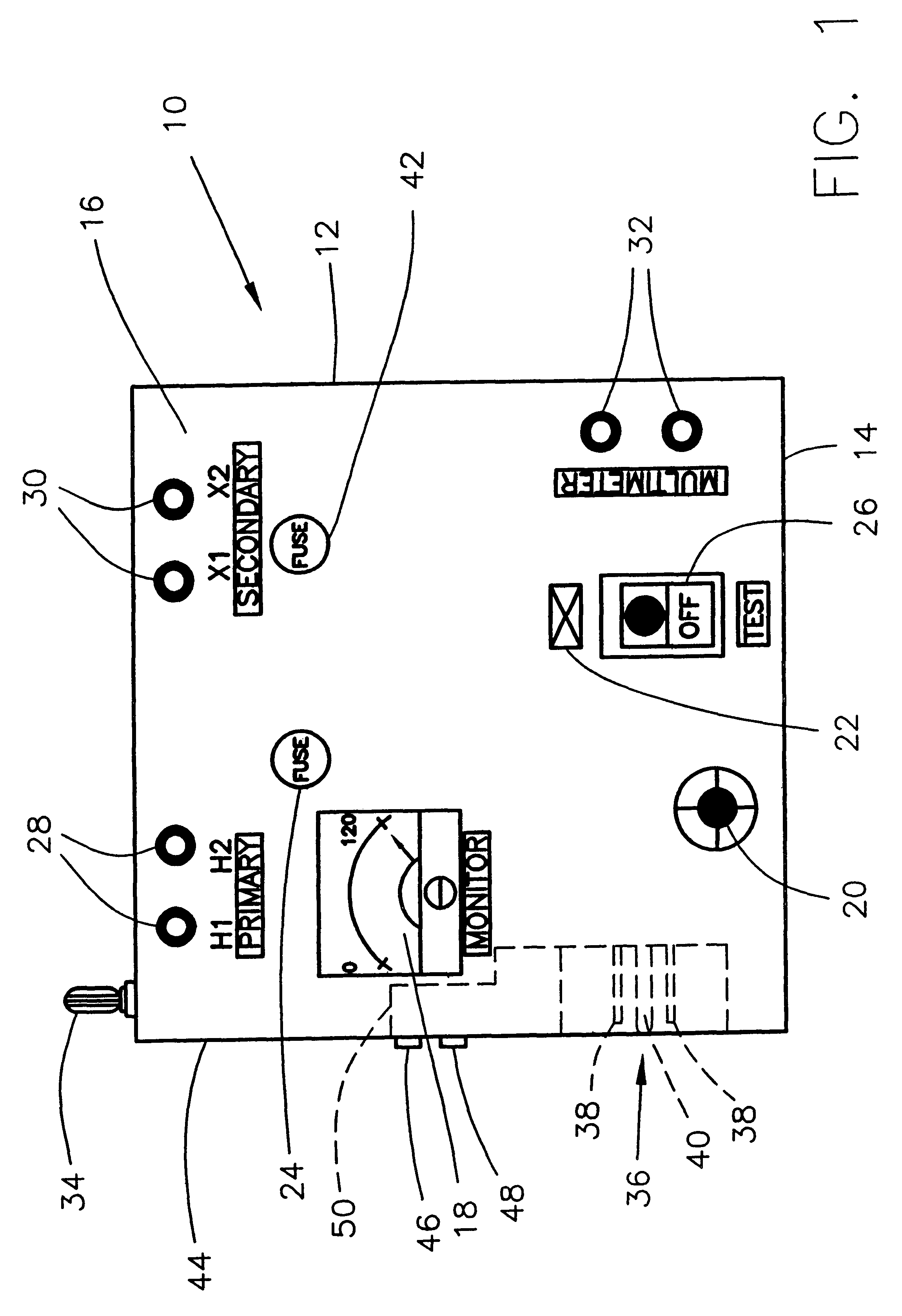
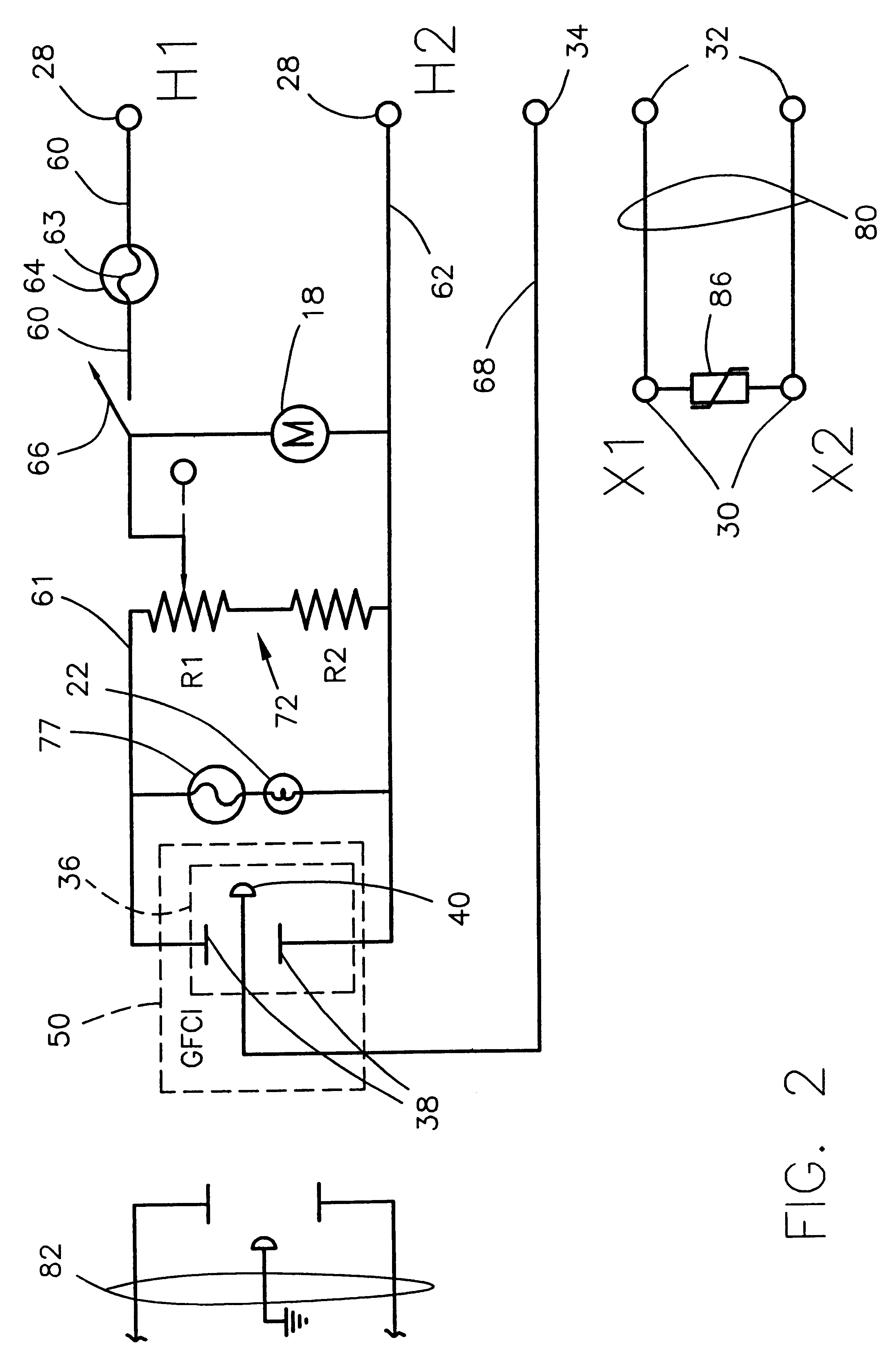
The test control assembly typically is contained within a housing or box 12. The housing 12 encloses the circuitry illustrated in and described later with respect to FIG. 2.

The housing 12 is a box advantageously made of an insulating material such as a high dielectric plastic. Disposed on one of the largest sides 16 of the box 12, is a voltmeter 18 of conventional design and having a pref...


PUM


Abstract

This transformer test control device permits testing of an electrical transformer as installed on a power pole without connecting any high voltage of the power distribution line to the transformer, thereby significantly enhancing the safety of the lineman during the testing procedure. A test control device for controlling the testing of an electrical transformer combines a visual indicator acting as both a power-on indicator and a fuse tester, a voltmeter, a voltage adjustment control, an operator control switch and a fuse as well as terminals for connecting both to an alternating current electrical supply and to the terminals of the primary coil of a transformer to be tested. Additionally, the test control device includes terminals for connecting the device and a secondary circuit to selected output terminals of the secondary coil of the transformer and additional terminals for receiving and retaining the contact portions of voltmeter test probes. The test control device simplifies the transformer testing and aids the lineman in testing while maintaining high standards for safety practices and, especially, during adverse weather conditions. This device may be embodied to include a dedicated second voltmeter. The test control device may be powered by either normal 120 volt line voltage or the output of a power inverter connected to the electrical system of a truck or other motor vehicle in those areas without readily available 120 volt AC power.

Description

This invention relates to apparatus for testing electrical transformers and, more specifically, to testing electrical transformers in a manner and at voltages to enhance the safety of the personnel working with such equipment.Transformers are installed by an electric utility provider at various intervals along electrical distribution power lines and, especially, at points at which electrical voltage is reduced further from transmission line voltage to consumer line voltage. An electrical utility power provider installs transformers. From time to time, these transformers may be damaged by natural forces such as lightning strikes or wind damage, animals or birds, and human factors including vehicles knocking down power lines, any of which can lead to short circuits or overheating.Once a transformer in an electrical power distribution system is damaged and fails, the customers "downline" therefrom are deprived of electrical power and service.Any power outage may be caused by one or mor...

Claims


Application Information

Patent Timeline
Patent Type & Authority Patents(United States)
IPC IPC(8): G01R29/00G01R29/20
CPCG01R29/20G01R31/027G01R31/62
Inventor WHITE, XENIA BURDETTE
Owner WHITE XENIA BURDETTE
Why Eureka
Try Eureka