Housing For An Electronic Device

a technology for electronic devices and housings, applied in the direction of instruments, computing, support structure mounting, etc., can solve the problems of relative complexity, and achieve the effect of improving security and enhancing locking strength

Inactive Publication Date: 2009-10-29
WISTRON CORP
View PDF3 Cites 11 Cited by
  • Summary
  • Abstract
  • Description
  • Claims
  • Application Information

AI Technical Summary

Benefits of technology

[0019]In the housing for an electronic device according to the invention, the locking mechanism having a simple structure can be simultaneous

Problems solved by technology

Although such a structure provides a stronger locking strength

Method used


Image

  • Housing For An Electronic Device
  • Housing For An Electronic Device
  • Housing For An Electronic Device

Examples


Embodiment Construction

[0035]Through a description of the preferred embodiment, the technical means employed by the present invention to achieve the intended object, and the advantageous effects contemplated thereby, can be better understood and appreciated. However, it is noted that the accompanying drawings are for illustrative purpose and reference only, and are not intended to limit the scope of the present invention.

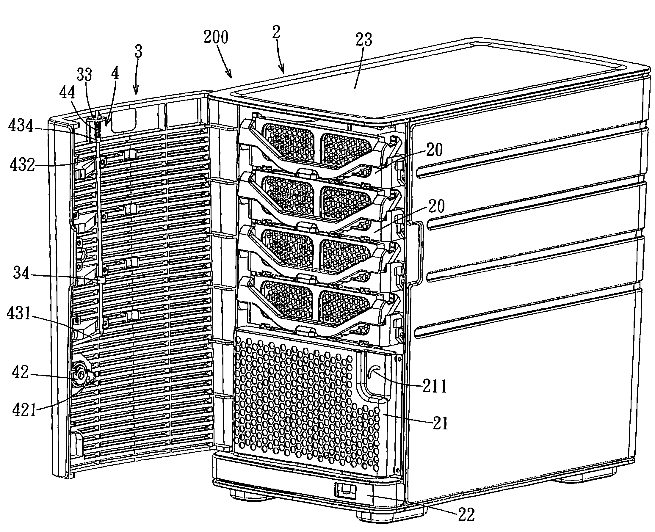
[0036]FIGS. 4, 5, and 6 show the preferred embodiment of a housing 200 of an electronic device according to the present invention. The electronic device may be a server or a computer device. The housing 200 of the electronic device includes a housing body 2, a cover 3, and a locking mechanism 4.

[0037]The housing body 2 includes a plurality of drawable hard disk cases 20 disposed therein for receiving hard disks (not shown), a front panel 21 disposed below the hard disk cases 20, a bottom frame 22 disposed at a bottom side of the front panel 21, and an outer peripheral panel 23 disposed ab...


PUM


Abstract

A housing for an electronic device includes a housing body with a front panel and an outer peripheral panel. A cover is coupled to the housing body, is located in front of the front panel, and is formed with an opening. A locking mechanism includes an actuating member disposed in the opening, a transmitting member coupled to the actuating member and disposed on a rear face of the cover, and a rod member disposed on the rear face of the cover. The transmitting member has a catch portion disposed to be retained at the front panel, and an arm portion. The actuating member drives the transmitting member to rotate such that the catch portion is retained at the front panel and the arm portion pushes one end of the rod member to move, thereby enabling the other end of the rod member to be retained at the outer peripheral panel.

Description

CROSS-REFERENCE TO RELATED APPLICATION[0001]This application claims priority of Taiwanese Application No. 097207166, filed on Apr. 25, 2008.BACKGROUND OF THE INVENTION[0002]1. Field of the Invention[0003]The invention relates to a housing for an electronic device, more particularly to a locking mechanism of a housing for an electronic device.[0004]2. Description of the Related Art[0005]As shown in FIGS. 1, 2 and 3, a housing 1 of a conventional electronic device includes a housing body 11, a cover 12 connected pivotally to a front side of the housing body 11, and a lock 13 disposed on the cover 12. The housing body 11 includes a front panel 111 for retaining a hook 131 of the lock 13. The front panel 111 has a curved guide slot 112 for extension of the hook 131 therethrough. When a user inserts a key (not shown) into a key slot 130 in the lock 13 and brings the hook 131 of the lock 13 to rotate in a direction indicated by the arrow VI (see FIG. 3) such that the hook 131 is rotated t...

Claims


Application Information

Patent Timeline
IPC IPC(8): H05K7/16
CPCG06F1/181
Inventor LEE, TUNG-PINGKUO, YU-LING
Owner WISTRON CORP
Why Eureka
Try Eureka