Pump

Inactive Publication Date: 2009-10-29
YEO JUI HWA
View PDF11 Cites 10 Cited by
  • Summary
  • Abstract
  • Description
  • Claims
  • Application Information

AI Technical Summary

Benefits of technology

[0014]Desirably, the hand pump is operatively connected to a plunger slidably housed within the reservoir, whereby upon actuation of the plunger, the drawn fluid can be expelled back out through the orifice of the reservoir. The plunger is preferably arranged between the air intake valve and the reservoir, and includes an elongate tube allowing air flow between the reservoir and the bulb. The plunger is preferably actuated whilst simultaneously closing the air release valve. This helps to prevent the

Problems solved by technology

Current devices suffer from the disadvantage that the pump cannot be repeatedly compressed and decompressed, to draw more fluid, because each compression will force the dra

Method used


Image

  • Pump
  • Pump
  • Pump

Examples


Example

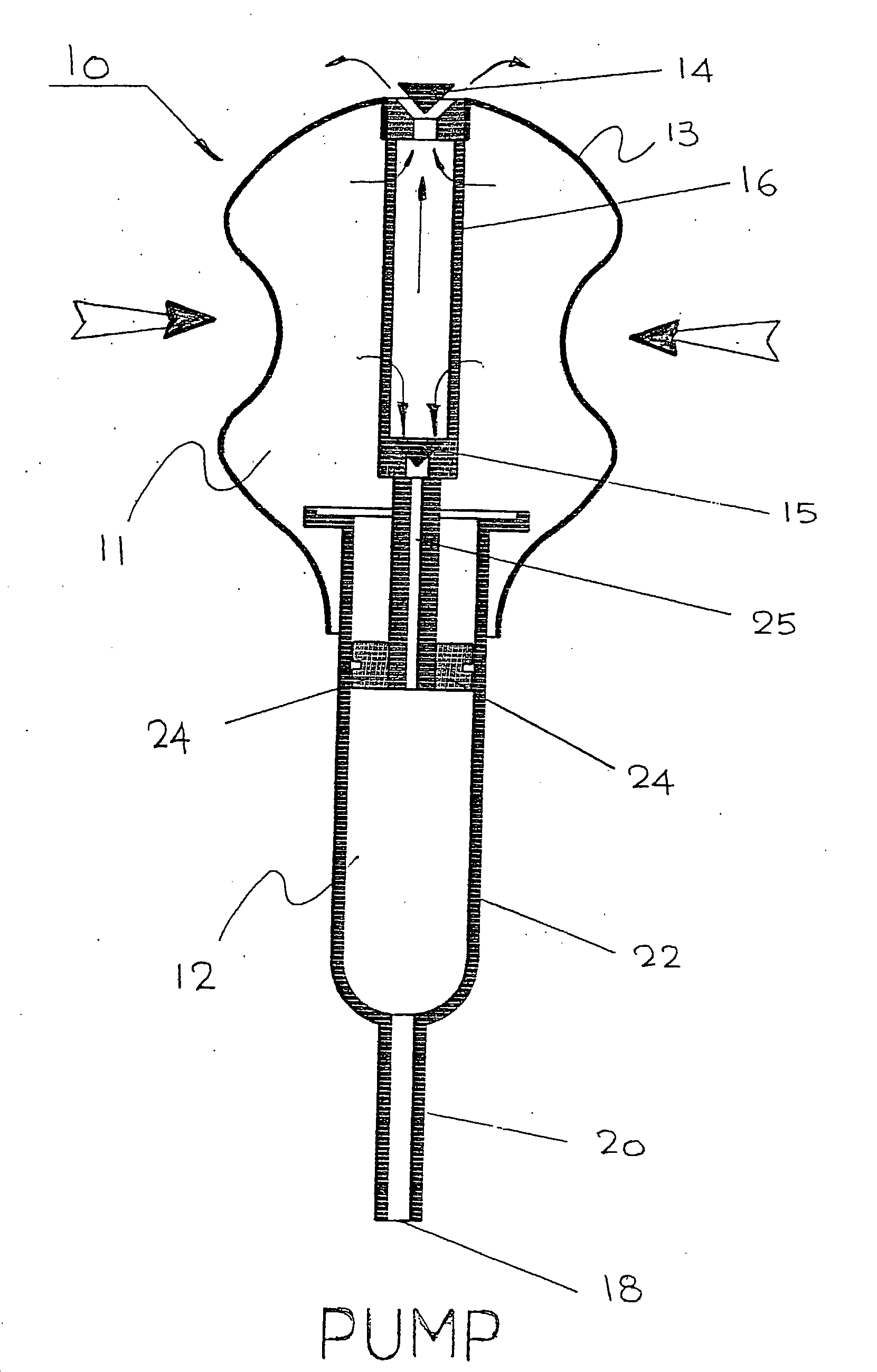
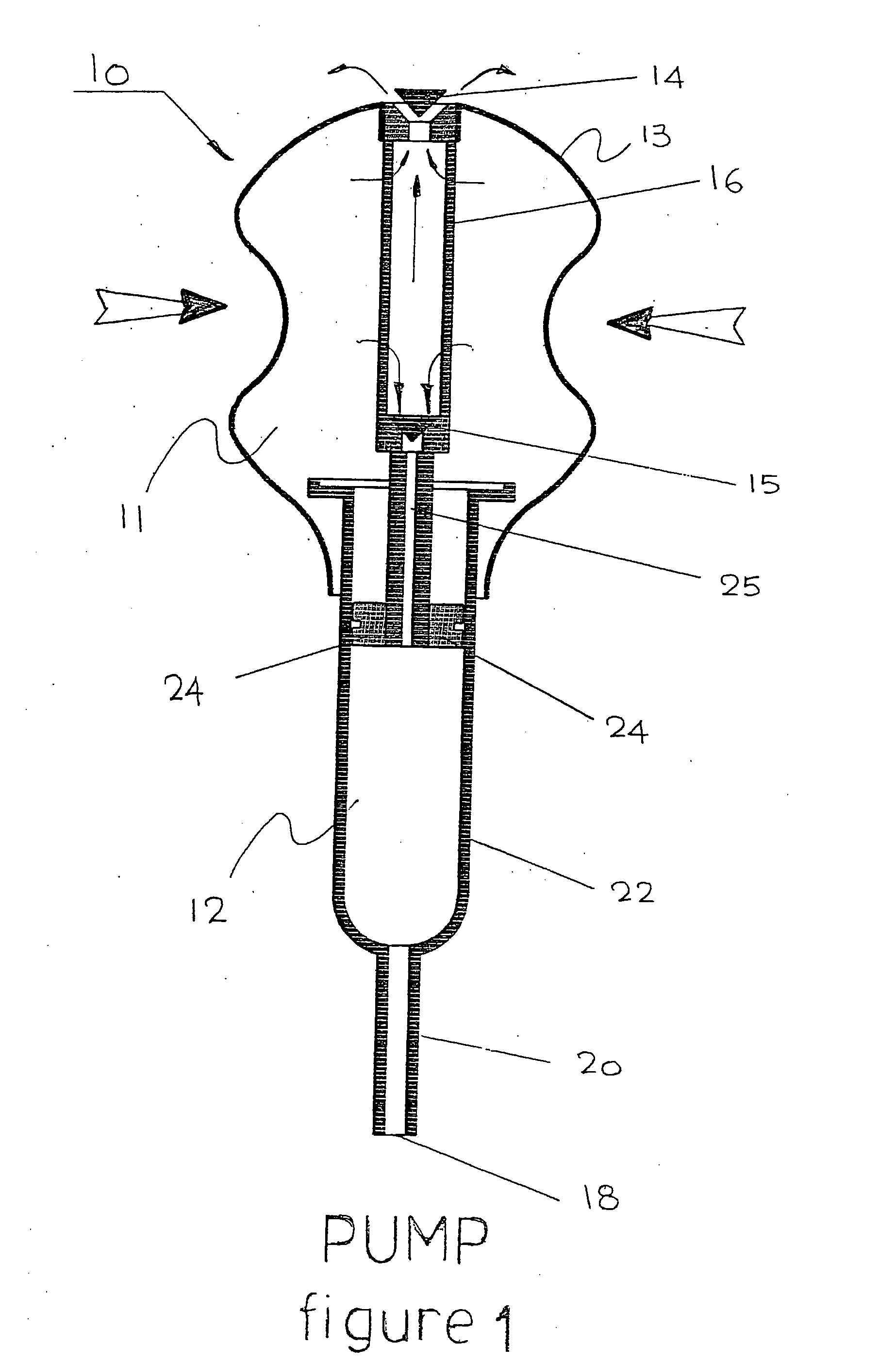
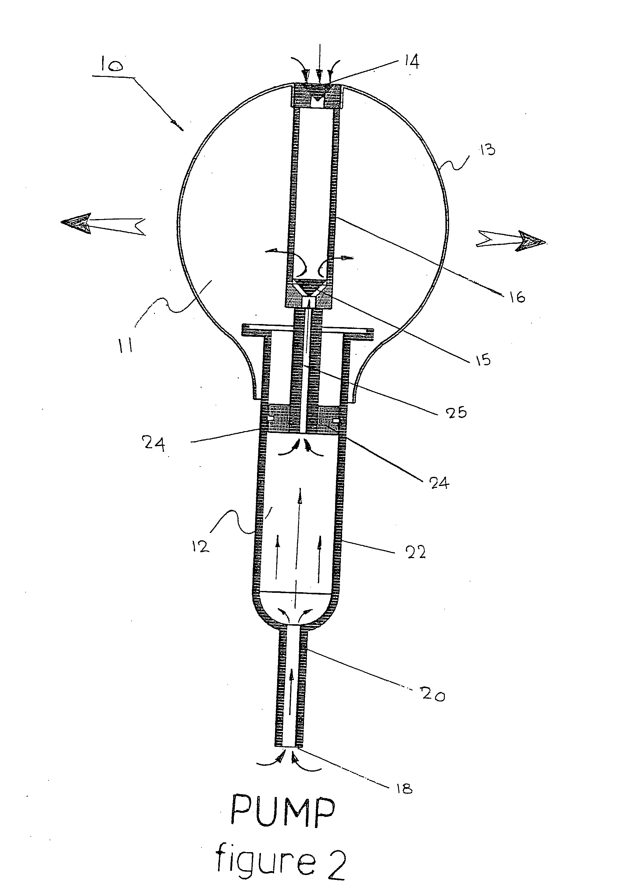
[0020]FIG. 1 shows a fluid drawing device 10 comprising a hand pump 11 connected to a fluid reservoir 12. The hand pump 11 comprises a squeeze bulb 13, with an air release valve 14 in the wall of the squeeze bulb 13, and an air intake valve 15. The air release valve 14 and air intake valve 15 are rigidly connected by bridging piece 16, which does not interfere with air flow between the valves 14, 15 and the bulb 13.

[0021]The fluid reservoir 12 has an inlet / outlet orifice 18 through which fluid can be drawn into and expelled from the reservoir 12. The reservoir 12 further comprises a capillary tube 20 extending from the orifice 18 and a larger cylindrical tube 22. The tubes 20, 22 will typically be formed from glass or plastic.

[0022]A plunger 24 is slidably fitted and sealingly engages within the cylindrical tube 22. The plunger 24 is connected to the hand pump 11 through the bridging piece 16, at the air intake valve 15. The plunger 24 includes a central tubular rod 25 connected to ...


PUM


Abstract

A fluid drawing device (10) comprising a hand pump (11) connected to a fluid reservoir (12). The reservoir (12) has an inlet/outlet orifice (18) through which fluid can be drawn into and expelled from the reservoir (12). The pump (11) comprises a squeeze bulb (13) with an air release valve (14) in its wall and an air intake valve (15). Compressing the bulb (13) releases the air to the atmosphere through the release valve (14), subsequent decompression of the bulb (13) draws air through the intake valve (15) from the reservoir (12) reducing the pressure in it to draw fluid through the orifice (18) into the reservoir (12). Pushing a plunger (24) slidably housed within the reservoir (12) expels the fluid out through the orifice (18).

Description

FIELD OF THE INVENTION[0001]The present invention relates to devices for drawing fluid.BACKGROUND OF THE INVENTION[0002]There are a wide range of circumstances in which fluid must be transferred from one place to another. For instance, in a scientific laboratory, a pipette is commonly used to transfer a fluid (such as blood) from a beaker to a test tube, or from one test tube to another.[0003]Current devices for drawing fluid generally include a reservoir for storing the fluid, a fluid inlet / outlet orifice through which fluid can be drawn, and a compressible hand pump. In use, the pump is compressed, which forces air out through the inlet / outlet orifice. The orifice is then inserted into the fluid source (from which fluid is to be drawn), and the pump allowed to decompress. This draws air from the reservoir, reducing the pressure in the reservoir and thereby drawing fluid in through the inlet / outlet orifice. To expel fluid from the device, the pump is compressed again. This increase...

Claims


Application Information

Patent Timeline
IPC IPC(8): F04B43/00B67D7/60
CPCB01L3/021B01L2400/0478B01L2400/0481F04F3/00F04B9/14F04B33/00F04B45/02B01L2400/0605
Inventor YEO, JUI HWA
Owner YEO JUI HWA
Why Eureka
Try Eureka