Cash box system for a vending machine

Inactive Publication Date: 2009-11-05
RTB
View PDF6 Cites 8 Cited by
  • Summary
  • Abstract
  • Description
  • Claims
  • Application Information

AI Technical Summary

Benefits of technology

[0007]An object of the invention is to provide a cash box emptying system having a cash box for vending machines in which the changing of the...

Problems solved by technology

The known locking mechanism prevents insertion of an emptied cash box in the cash box compartment how...

Method used


Image

  • Cash box system for a vending machine
  • Cash box system for a vending machine
  • Cash box system for a vending machine

Examples


Embodiment Construction

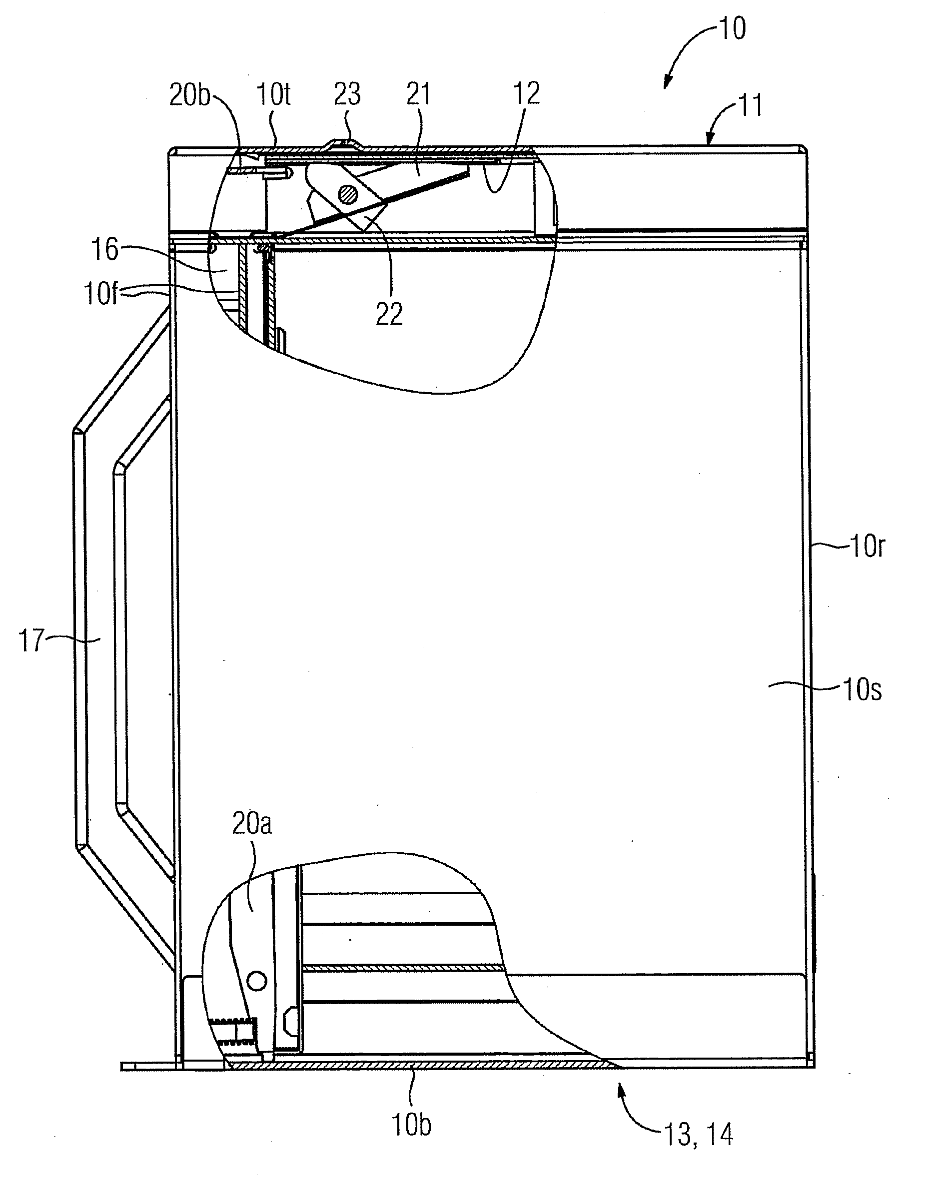
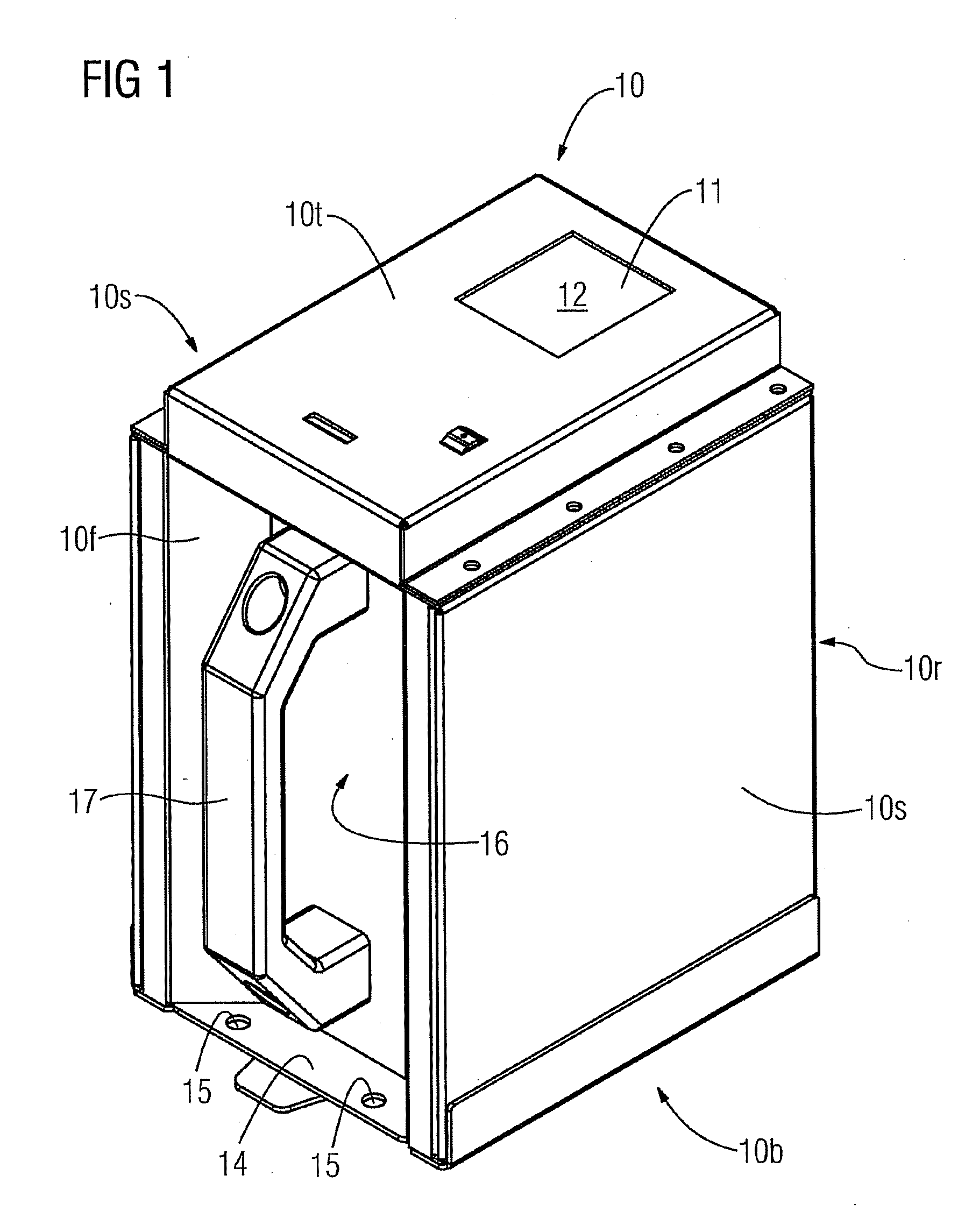
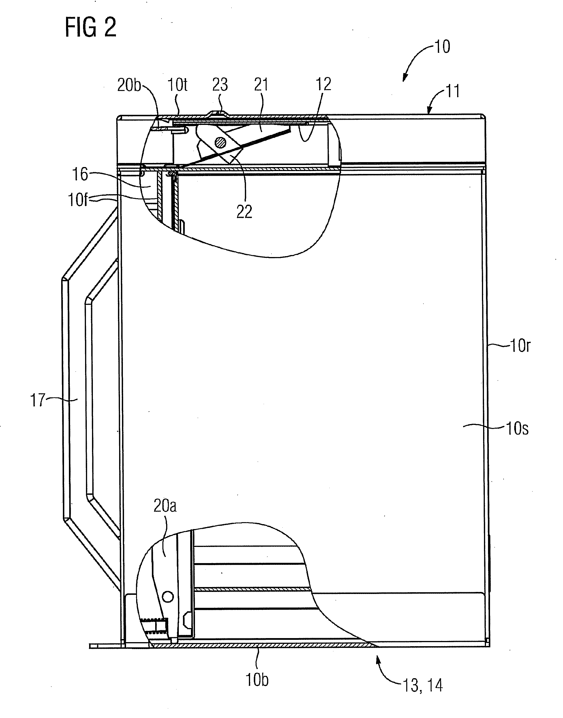
[0038]According to FIG. 1 to FIG. 4 a cash container 10 is constructed so as to be box-shaped and comprises a top wall 10t, a front wall 10f, a back wall 10r, two side walls 10s and a bottom wall 10b. In the position inserted in a vending machine, for instance a parking ticket vending machine, the top wall 10t is located at the top and the bottom wall 10b at the bottom. The top wall 10t comprises an inlet opening 11 for cash, in particular in the form of coins, which can be closed by a cover 12 constructed as a displaceable slide. The bottom wall 10b includes an emptying opening 13 which can be closed by a displaceable door 14. To insert or remove the cash container 10 in or from a vending machine a c-shaped, vertically oriented handle 17 is immovably secured to the front wall 10f by means of two screws. The handle 17 is designed as a plastics material part with a rectangular cross-section at least in certain sections and is secured in a trapezoidal indentation 16 in the front wall ...


PUM


Abstract

A cash box system with a cash container for receiving cash is described. The cash container has an inlet opening which can be closed by a cover and a locking mechanism having a locked state in which the cover is locked in a position closing the inlet opening, and a release state in which the cover is unlocked and can be brought in a position to release the inlet opening. The locking mechanism is configured such that it is forcibly transferred from the locked state to the release state when the cash container is emptied. The cash box system is preferably for a vending machine in which the cash container is inserted.

Description

CROSS REFERENCE TO RELATED APPLICATIONS[0001]This application is the US National Stage of International Application No. PCT / EP2007 / 058709 filed Aug. 22, 2007 and claims the benefit thereof. The International Application claims the benefits of German Patent Application No. 10 2006 055 085.4 DE filed Nov. 21, 2006, both of the applications are incorporated by reference herein in their entirety.FIELD OF INVENTION[0002]The invention relates overall to a cash box system having a cash container for receiving cash, having a vending machine, in particular a parking ticket vending machine, in which the cash container can be inserted, having a collecting box for emptying the cash container and having a service vehicle, in which the collecting box is arranged.BACKGROUND OF INVENTION[0003]Vending machines having cash containers for receiving cash are used in a wide range of variants. A user can acquire a large number of goods and / or services from such vending machines against payment of cash. T...

Claims


Application Information

Patent Timeline
IPC IPC(8): G07F9/10B65D45/00B65D25/28
CPCG07D9/00Y10S902/13Y10S902/09G07F9/06
Inventor BRAUKMANN, ERWINJOVIC, SIME
Owner RTB
Why Eureka
Try Eureka