

Elastic Member for Pushbutton Switch
a technology of elastic member and pushbutton switch, which is applied in the direction of contact mechanism, electrical equipment, emergency protective devices, etc., can solve the problems of difficult adjustment of peak stroke, inability to gain the stroke sb>1/b> intended in the elastic member, etc., and achieves easy adjustment of peak stroke and gentle increase of resilient load
- Summary
- Abstract
- Description
- Claims
- Application Information
AI Technical Summary
Benefits of technology
Problems solved by technology
Method used
Image

Examples
first embodiment
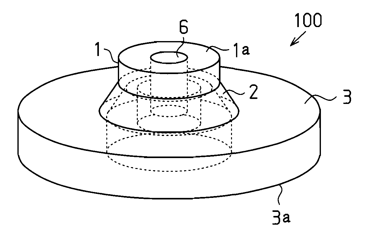
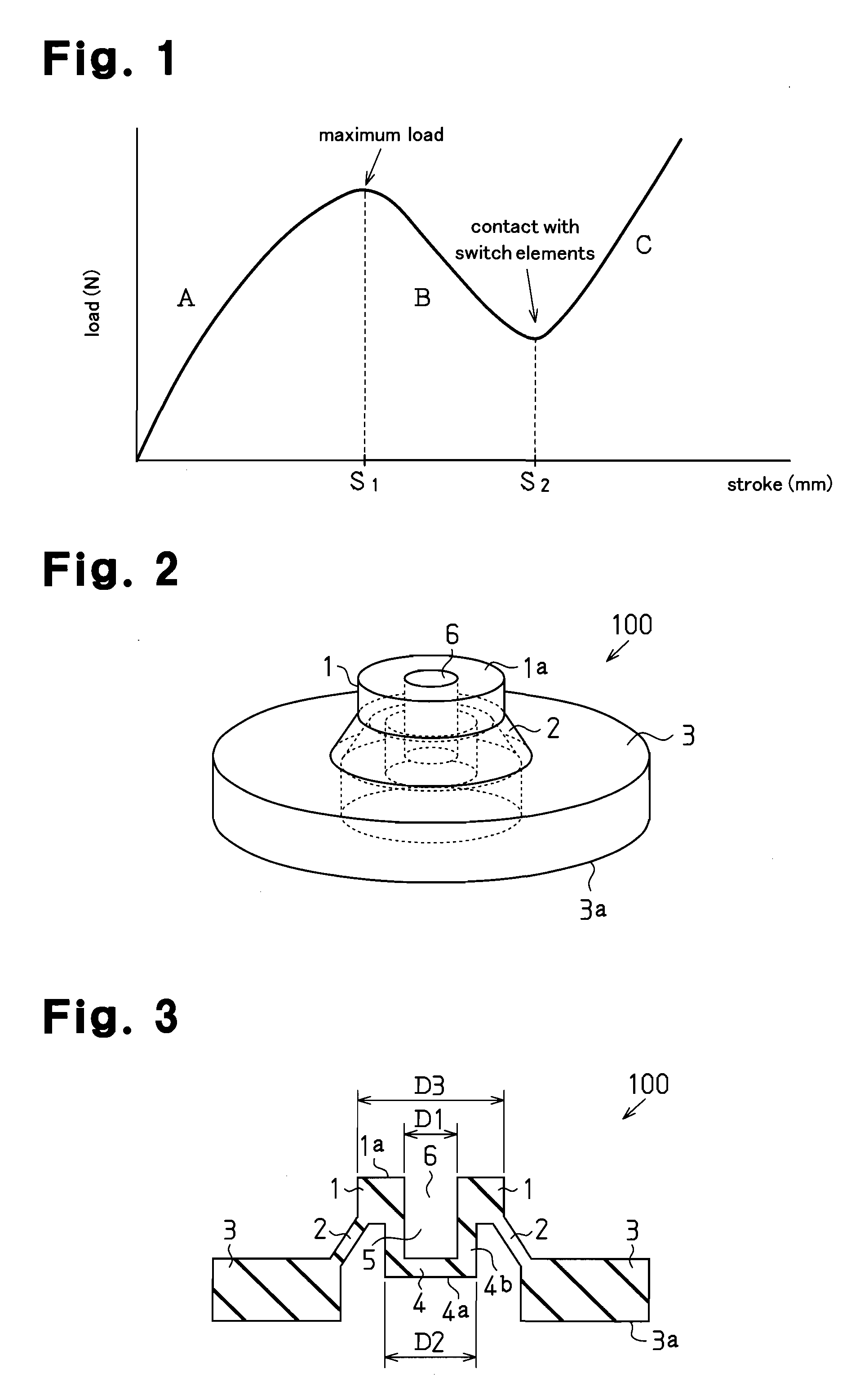
[0029]FIGS. 2 and 3 are a perspective view and a longitudinal cross-sectional view, each showing an elastic member 100 according to a first embodiment of the present invention.
[0030]The elastic member 100 is provided with an annular plate-shaped base portion 3, a connection portion 2 which is thin and extends diagonally upward from the inner periphery of the base portion 3, and a substantially disc-shaped pressing portion 1 which is supported above the base portion 3 by the connection portion 2. According to the present embodiment, as shown in FIG. 2, the connection portion 2 is shaped like a reverse funnel (a truncated cone) and converges upward. The pressing portion 1 is provided with a protrusion which protrudes downward from the lower surface of the pressing portion 1, that is to say, a pusher 4. The lower surface 4a of the pusher 4 is located above the lower surface 3a of the base portion 3. A hollow portion 5 is created inside the pusher 4 and an opening 6 which continues from...
second embodiment
[0042]FIG. 7 is a perspective view showing the elastic member 200 according to a second embodiment of the present invention.
[0043]The elastic member 200 is provided with a pair of prism shaped base portions 3 which are placed at a distance from each other, thin plate shaped connection portions 2 which respectively extend diagonally upward from the upper end of these two base portions 3 which face each other, and a pressing portion 1 shaped like a rectangular plate which is supported above the base portions 3 by the connection portions 2. The pressing portion 1 is provided with a substantially prism shaped pusher 4 which protrudes downward from the lower surface of the pressing portion 1. The lower surface 4a of the pusher 4 is located above the lower surface 3a of the base portions 3. A hollow portion 5 having openings on the two sides of the pusher 4 is created in the pusher 4.
third embodiment
[0044]FIG. 8 is a perspective view showing an elastic member 300 according to a third embodiment of the present invention.
[0045]The elastic member 300 has the same structure as the elastic member 200, except that an opening 6 which continues from the hollow portion 5 of the pusher 4 is created on the upper surface 1a of the pressing portion 1. The hollow portion 5 of the pusher 4 and the opening 6 of the pressing portion 1 have a constant lateral cross-sectional form. As shown in FIG. 8, the opening 6 of the pressing portion 1 and the hollow portion 5 of the pusher 4 make the pressing portion 1 and the pusher 4 of a U shape as a whole.
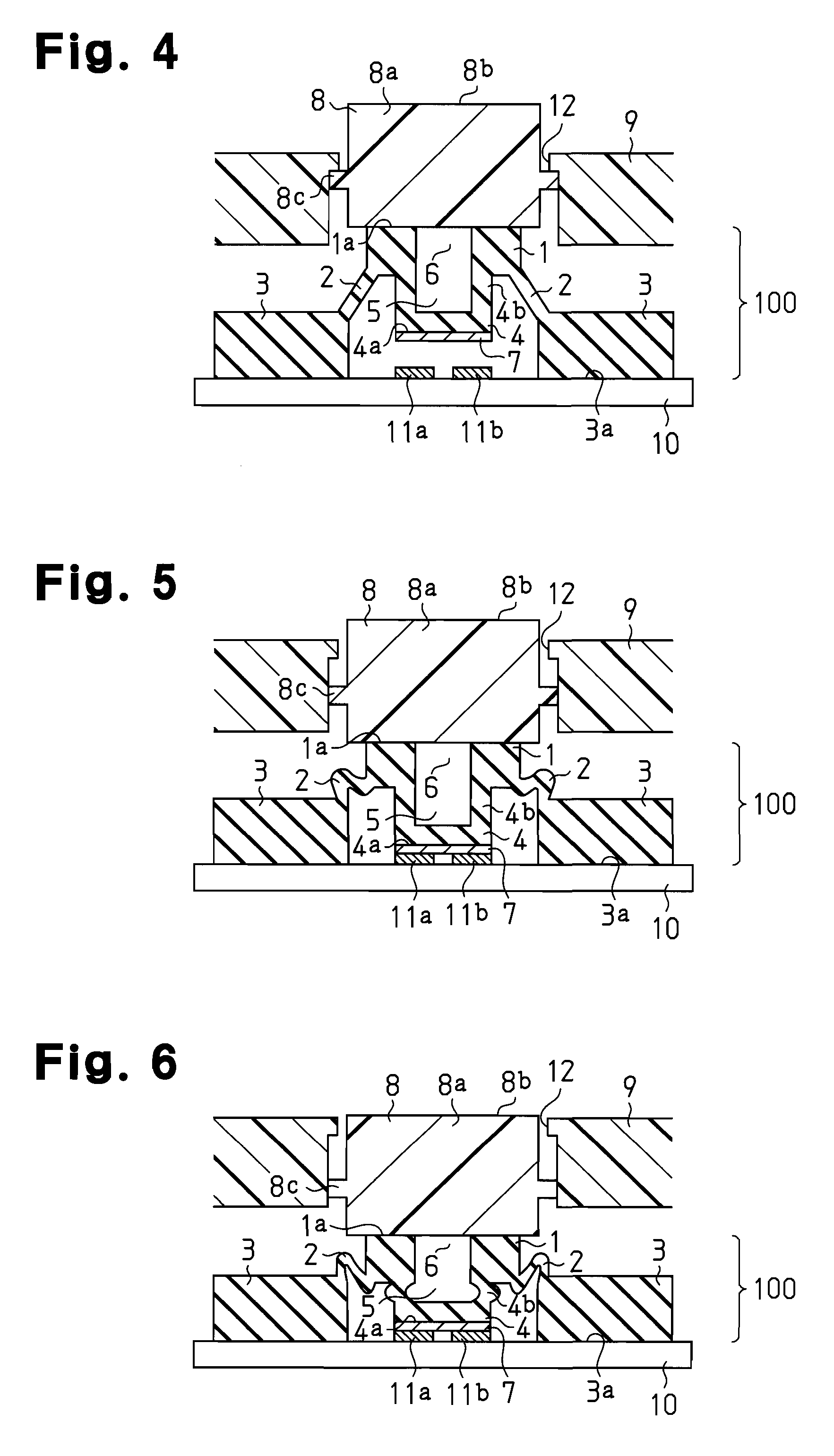
[0046]In the case where the elastic member 200 or 300 is incorporated in the structure for a pushbutton switch for use, the connection portions 2 elastically change in form and buckle when the pressing portion 1 of the elastic member 200 or 300 is pressed, so that the lower surface 4a of the pusher 4 makes contact with the switch elements (not shown) o...
PUM
 Abstract
Description
Claims
Application Information