
Method and tool for forming non-circular holes using a selectively coated electrode

a selective coating and non-circular hole technology, applied in the direction of manufacturing tools, electrical-based machining electrodes, machining electrodes, etc., can solve the problems of low process efficiency of cyclic dwelling methods and none of the above methods are directed to producing non-circular holes

Active Publication Date: 2009-11-12
GENERAL ELECTRIC CO
View PDF10 Cites 26 Cited by
  • Summary
  • Abstract
  • Description
  • Claims
  • Application Information

AI Technical Summary

Problems solved by technology

The cyclic dwelling method is very low in process efficiency compared to shaped-tube electrochemical machining (STEM) drilling of substantially straight-walled holes because of the long time required for drilling each bulb individually by cyclic tool dwelling.
None of the above methods are directed to producing a non-circular hole from the pre-formed, substantially straight-walled (circular) hole.

Method used


Image

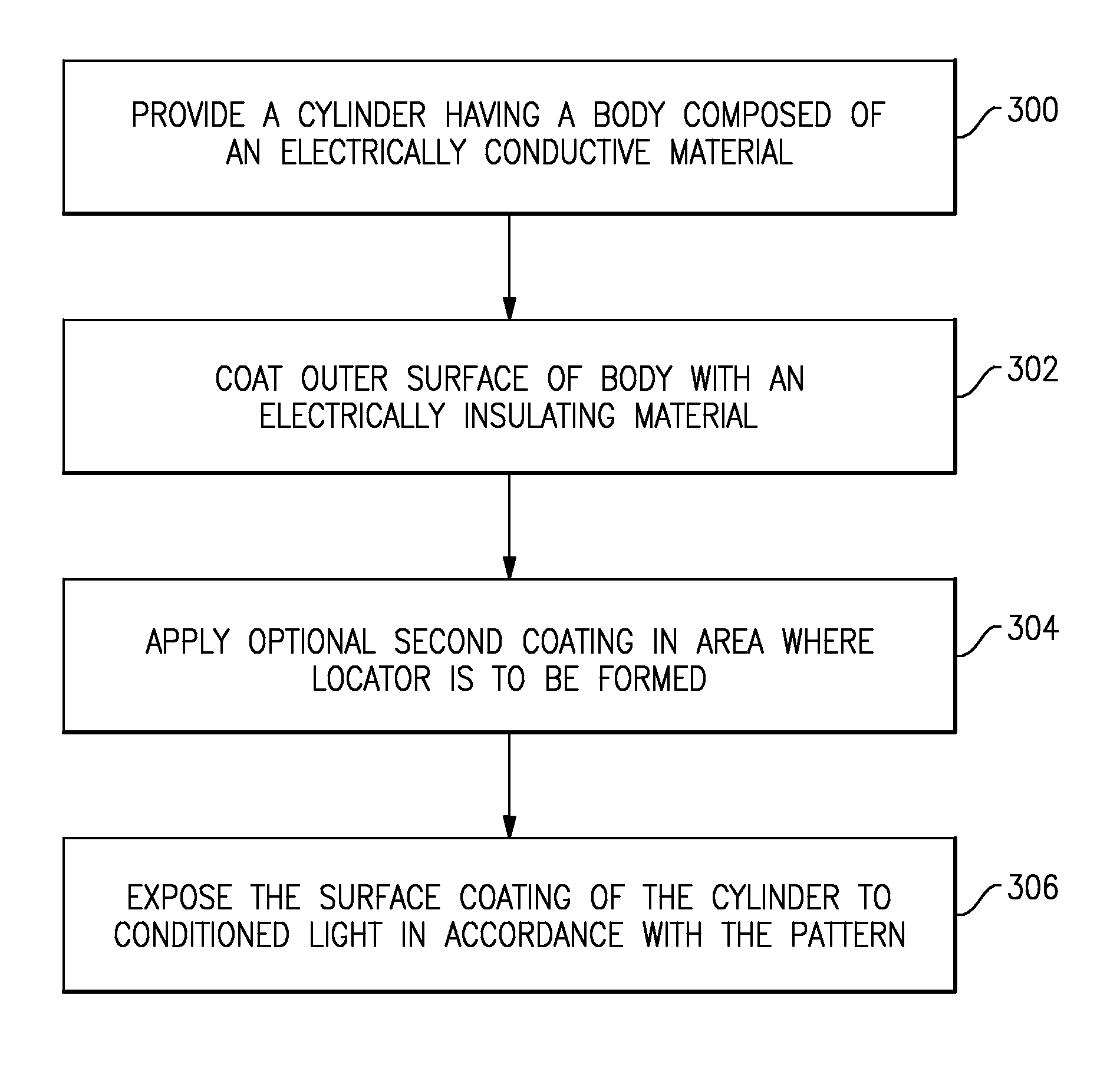
  • Method and tool for forming non-circular holes using a selectively coated electrode
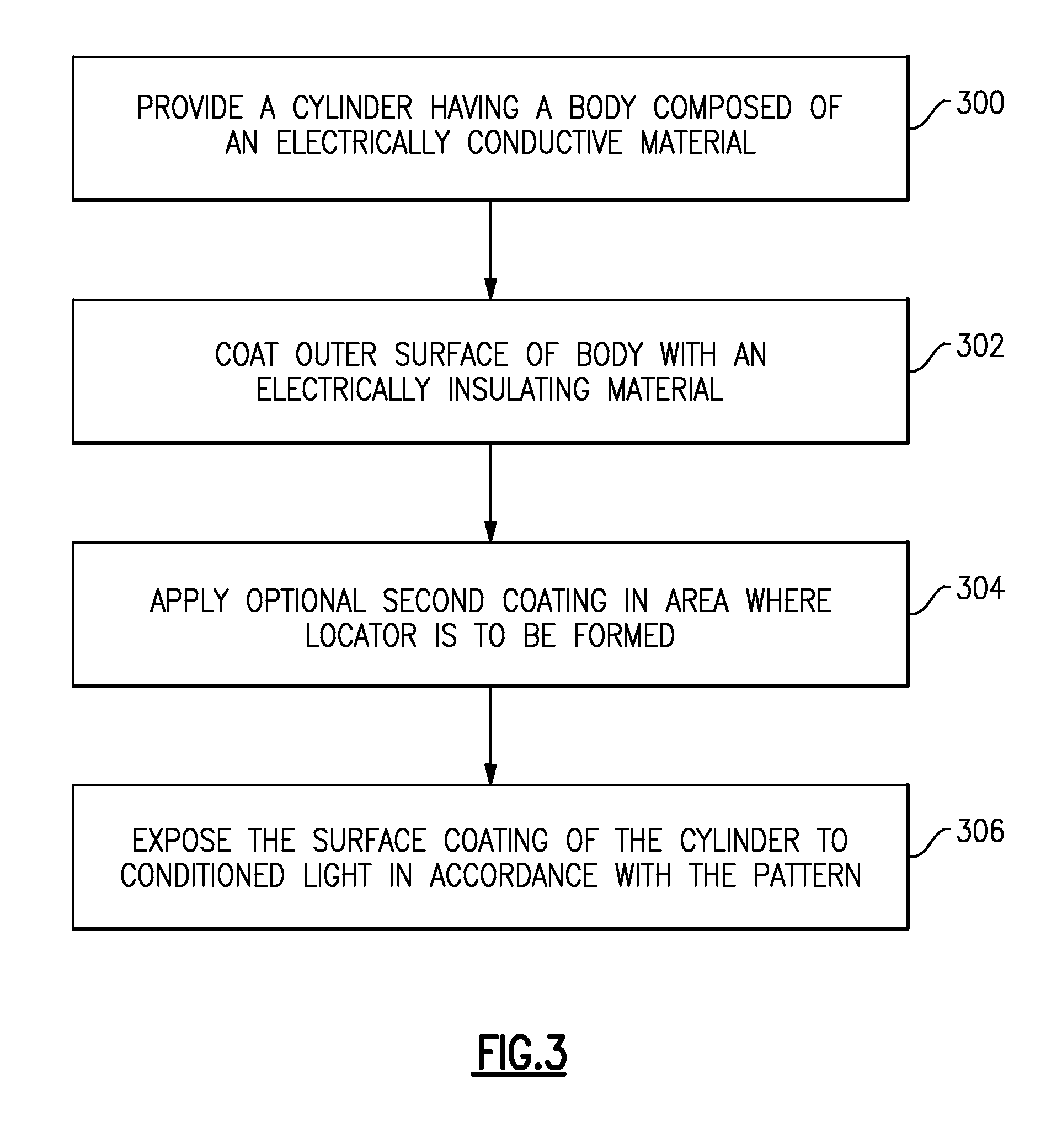
  • Method and tool for forming non-circular holes using a selectively coated electrode
  • Method and tool for forming non-circular holes using a selectively coated electrode

Examples


Embodiment Construction

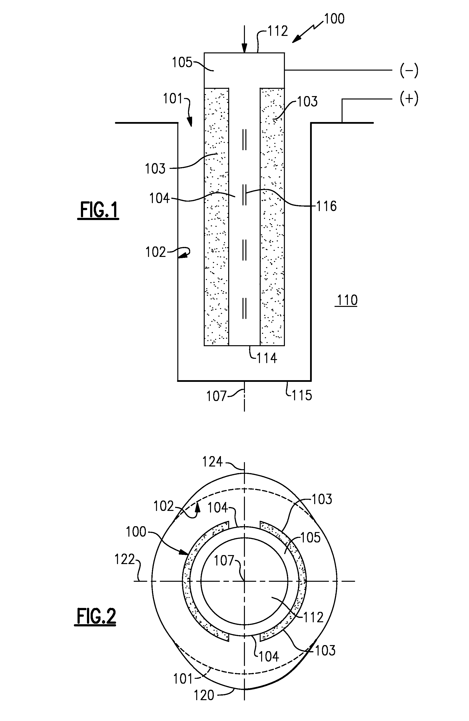
[0020]Referring to the drawings wherein identical reference numerals denote the same elements throughout the various views, FIG. 1 depicts an electrode 100 of the invention positioned in a circular hole 101 with a substantially straight wall 102 of an electrically conductive workpiece 110. The circular hole 101 can be produced using any known process, such as STEM, casting, and the like. FIG. 2 shows the electrode 100 of the invention after a non-circular hole 120 has been created from the circular hole 101. In the illustrated embodiment, the circular hole 101 has a substantially straight wall 102. However, the invention can be practiced by using the electrode 100 in a circular hole that does not have substantially straight walls. For example, the hole 101 can be circular, but the walls may have turbulators, such as ridges, and the like, formed thereon.

[0021]In the embodiments shown in FIGS. 1 and 2, the electrode 100 comprises a hollow cylinder 105 made of an electrically conductiv...


PUM

PropertyMeasurementUnit
Electrical conductivityaaaaaaaaaa
Electrical conductoraaaaaaaaaa

Abstract

An electrochemical machining process for forming a non-circular hole from a substantially circular hole within a workpiece using an electrode. The electrode is made of an electrically conductive material and has insulated areas in which the electrically conductive material is coated with an insulating material, and exposed areas of metal or conductive material. The insulated areas and exposed areas extending in rows substantially along a longitudinal axis of the electrode. The electrode is first positioned in a substantially circular hole. An electric current is then applied to the electrode to electrochemically remove a predetermined amount of material from the substantially circular hole to form a non-circular hole. A variety of different non-circular shapes are achievable using the process.

Description

BACKGROUND[0001]The invention relates to a tool and a method used in electrochemical machining. More particularly, the invention relates to a tool and method for forming non-circular holes from pre-formed circular holes by selectively removing insulating material on the surface of the tool.[0002]A specialized adaptation of electrochemical machining, known as shaped-tube electrochemical machining (STEM), is used for drilling small, deep holes in electrically conductive materials. STEM is a noncontact electrochemical drilling process which can produce holes with aspect ratios as high as 300:1. It is the only known method which is capable of manufacturing the small, deep holes used for cooling blades of efficient gas turbines.[0003]The efficiency of a gas turbine engine is directly proportional to the temperature of turbine gases channeled from the combustor of the engine and flowing over the turbine blades. For example, for gas turbine engines having relatively large blades, turbine g...

Claims


Application Information

Patent Timeline
IPC IPC(8): B23H9/14B23H3/00B23H11/00
CPCB23H3/00B23H3/04C25F3/00B23H9/00B23H9/14B23H3/06
Inventor WEI, BINBUNKER, RONALD SCOTT
Owner GENERAL ELECTRIC CO
Learn More