Production Method of Liquid Crystal Display and Exposure Device for Alignment Treatment

a production method and exposure technology, applied in the manufacture of electrode systems, electric discharge tubes/lamps, instruments, etc., can solve the problems of increasing the number of alignment treatment times and the difficulty of alignment treatment itself, and achieve the effect of efficient and stable alignment treatmen

Active Publication Date: 2009-11-12
SHARP KK
View PDF5 Cites 9 Cited by
  • Summary
  • Abstract
  • Description
  • Claims
  • Application Information

AI Technical Summary

Benefits of technology

[0013]In order to overcome the problems described above, the present invention provides a production method of a liquid crystal display device, the production method being capable of efficiently and stably providing alignment treatment for an alignment film of the liquid crystal display device, in which a plurality of domains is formed in a pixel region.

Problems solved by technology

Therefore, in the scanning exposure, the number of times of the alignment treatment dramatically increases or the alignment treatment itself is difficult.

Method used


Image

  • Production Method of Liquid Crystal Display and Exposure Device for Alignment Treatment
  • Production Method of Liquid Crystal Display and Exposure Device for Alignment Treatment
  • Production Method of Liquid Crystal Display and Exposure Device for Alignment Treatment

Examples


embodiment 1

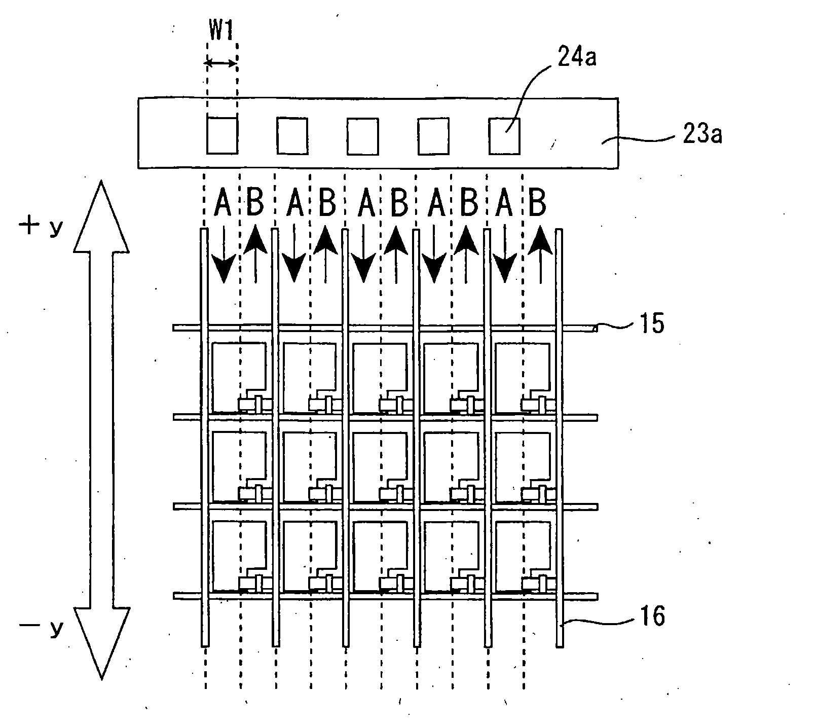
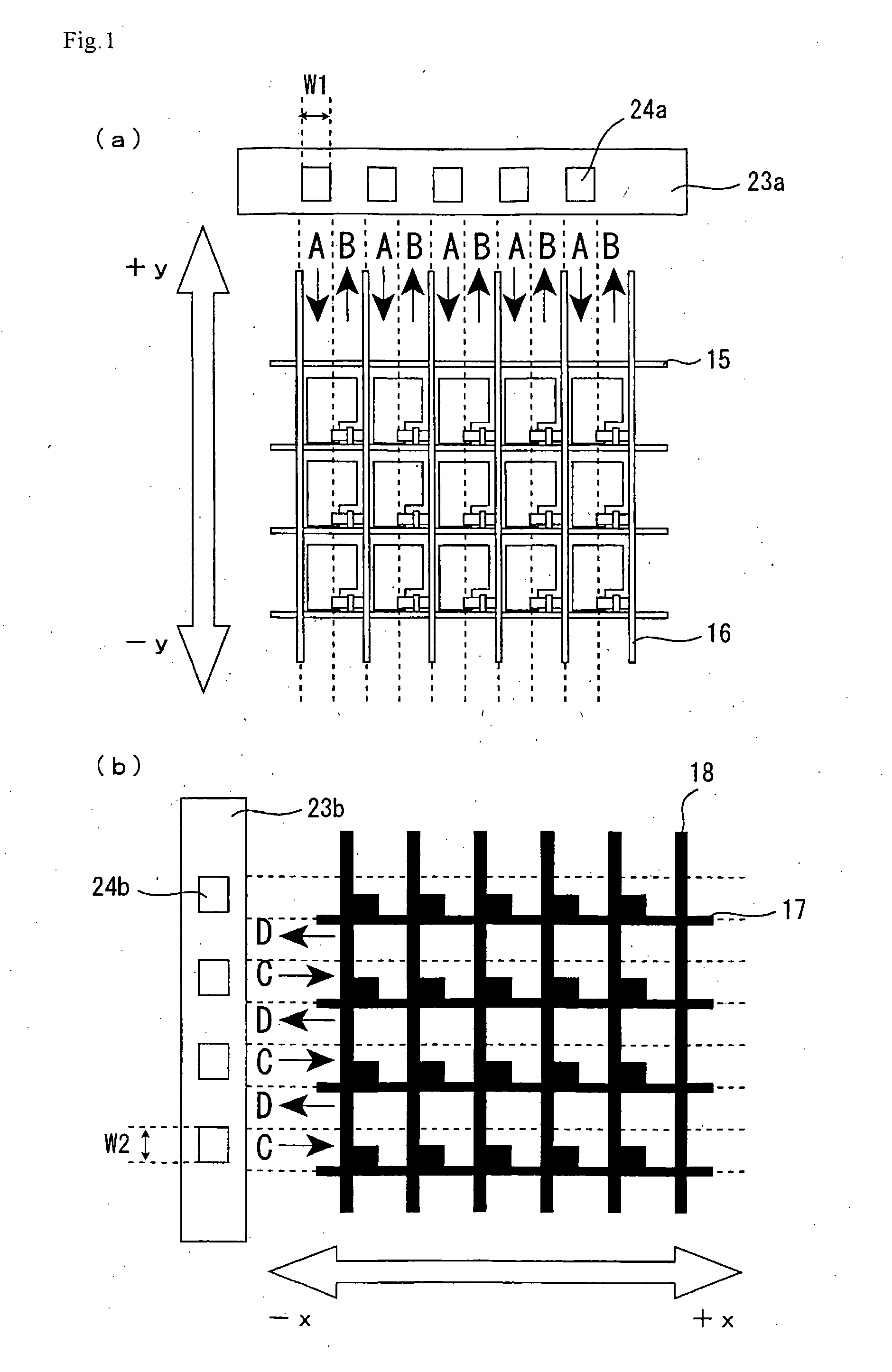
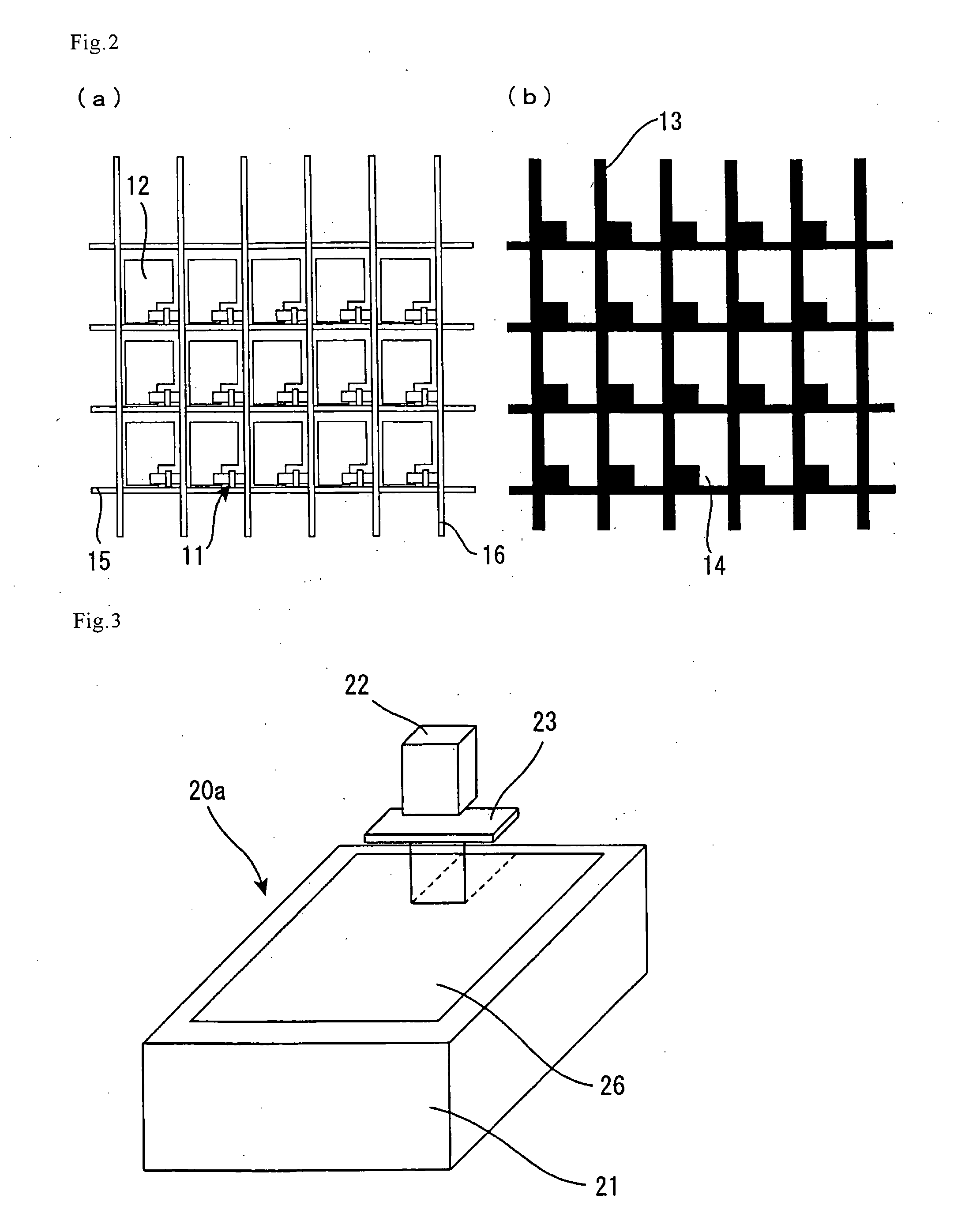
[0081]A production method of a liquid crystal display panel in 4VATN mode in Embodiment 1 according to the present invention is mentioned below with reference to FIGS. 1(a) to 3. FIG. 1(a) is a plane view schematically showing a light beam emitting direction to a photo-alignment film on a TFT array substrate in Embodiment 1. FIG. 1(b) is a plane view schematically showing a light beam emitting direction to a photo-alignment film on a CF substrate in Embodiment 1. FIG. 2(a) is a plane view schematically showing the TFT array substrate as the first substrate in Embodiment 1. FIG. 2(b) is a plane view schematically showing the CF substrate as the second substrate in Embodiment 1. FIG. 3 is a perspective view schematically showing an exposure device in Embodiment 1.

[0082]First, a pair of the first substrate and the second substrate each having no alignment film is prepared by a usual method. As the first substrate, a TFT array substrate shown in FIG. 2(a), which is prepared as follows, ...

embodiment 2

[0091]A production method of a liquid crystal display panel in 4VATN mode in Embodiment 2 according to the present invention is mentioned below with reference to FIG. 4. FIG. 4 is a perspective view schematically showing an exposure device in Embodiment 2. The liquid crystal display panel in 4VATN mode in Embodiment 2 is produced in the same manner as in Embodiment 1, except for the configuration of the exposure device and the embodiment of the scanning exposure. Therefore, overlapping contents between Embodiment 1 and Embodiment 2 are omitted.

[0092]First, the exposure device in Embodiment 2 is explained with reference to FIG. 4. As shown in FIG. 4, the exposure device 20b in Embodiment 2 has a configuration in which the exposure device 20a in Embodiment 1 further comprises the camera for image detection 25 for detecting a linear micropattern, such as the bus line (the scanning signal line or the data signal line) and the BM formed on the substrate. According to such a configuration...


PUM

PropertyMeasurementUnit
incident angleaaaaaaaaaa
angleaaaaaaaaaa

Abstract

To provide: a production method of a liquid crystal display device, the production method being capable of efficiently and stably providing alignment treatment for an alignment film of the liquid crystal display device, in which a plurality of domains is formed in a pixel region; and an exposure device for alignment treatment. A production method of a liquid crystal display device comprising: a first substrate; a second substrate facing to the first substrate; a liquid crystal layer provided between the substrates; a first alignment film provided on the liquid crystal layer side surface of the first substrate; and a second alignment film provided on the liquid crystal layer side surface of the second substrate, wherein the production method comprises subjecting the first alignment film and/or the second alignment film to scanning exposure continuously over a plurality of pixel regions, and the scanning exposure comprises exposing the first alignment film and/or the second alignment film while scanning an inside of each pixel region more than one time in antiparallel directions to form, in the each pixel region, regions for aligning liquid crystal molecules to the surface(s) of the first alignment film and/or the second alignment film in antiparallel directions.

Description

TECHNICAL FIELD[0001]The present invention relates to a production method of a liquid crystal display device and an exposure device for alignment treatment. More specifically, the present invention relates to a production method of a matrix-type liquid crystal display device which can provide high display quality by forming a plurality of domains in one pixel region. The present invention also relates to an exposure device for alignment treatment.BACKGROUND ART[0002]Liquid crystal display devices in TN (Twist Nematic) mode have well-balanced characteristics needed for display devices. For example, the devices have a low driving voltage and a relatively fast response speed, and are suitably used for color display because the devices provide monochrome display in principle. Therefore, such liquid crystal display devices in TN mode have been widely used for matrix-type liquid crystal display devices such as an active matrix-type liquid crystal display device and a simple matrix-type li...

Claims


Application Information

Patent Timeline
Patent Type & Authority Applications(United States)
IPC IPC(8): G02F1/1337H01J9/00
CPCG02F1/133753G02F2001/133757G02F2001/133738G02F1/133738G02F1/133757
Inventor HAKOI, HIROYUKIINOUE, IICHIROMIYACHI, KOICHI
Owner SHARP KK
Why Eureka
Try Eureka